
Abstract
BACKGROUND AND PURPOSE: Intracranial aneurysms with irregular shapes and blebs or secondary outpouchings have been correlated with increased rupture risk. The purpose of this study was to investigate possible associations between the local hemodynamics and the formation of blebs in cerebral aneurysms.
MATERIALS AND METHODS: Computational models of 20 cerebral aneurysms harboring 30 well-defined blebs were constructed from 3D rotational angiographies. Models representing the aneurysm before bleb formation were constructed by virtually removing the blebs from the anatomic models. Computational fluid dynamics simulations of the aneurysm before and after bleb formation were performed under pulsatile flows. Flow and WSS visualizations were used to analyze the local hemodynamics in the region of the aneurysm that developed the bleb.
RESULTS: Most blebs (80%) occurred at or adjacent to the aneurysm region with the highest WSS before bleb formation, and near the flow impaction zone. Most blebs (83%) were found in regions of the aneurysm previously subjected to high or moderate WSS and progressed to low WSS states after the blebs were formed. Most blebs (77%) were aligned or adjacent to the inflow jet, whereas 17% were aligned with the outflow jet, and only 6% were not aligned with the flow direction. In addition, 90% of the aneurysms had maximal WSS higher than or similar to the WSS in the parent artery.
CONCLUSIONS: Blebs form at or adjacent to regions of high WSS and are aligned with major intra-aneurysmal flow structures. Formation of blebs results in a lower WSS state with formation of a counter current vortex. These findings imply that locally elevated WSS could contribute to the focalized wall damage that formed these structures.
Abbreviations
- CFD
- computational fluid dynamics
- PCMR
- phase-contrast MR
- 3DRA
- 3D rotational angiography
- WSS
- wall shear stress.
Controversy exists regarding the mechanisms responsible for aneurysm development, growth, and rupture. Theories have been developed on the basis of the notion that the aneurysm wall endures ongoing injury that leads to an ultimate wall failure and rupture. For the theories, researchers have focused on possible factors involved in the causes of injury to the aneurysm wall. Previous studies have found that unruptured aneurysms tended to have large flow impingement regions (more dispersed inflow jets) and simple stable flow patterns, whereas ruptured aneurysms tended to have small impaction zones (more concentrated inflow jets) and complex or unstable intra-aneurysmal flow patterns.1 These findings suggest that elevated WSS caused by the impaction of a concentrated inflow jet may have a damaging effect on the arterial wall, which could cause an aneurysm to progress and rupture.
Aneurysm blebs have been identified as a factor for increased risk of future rupture in a number of clinical studies.2–4 Presence of multiple lobes or a daughter sac are more common in previously ruptured aneurysms than unruptured aneurysms.3 Tsukahara et al2 reported a global rupture rate of 3.42%/year and a rupture rate of 28.3%/year in aneurysms that contained blebs at the beginning of the observation period and observed that the likelihood of unruptured aneurysms to rupture was not exceedingly low, even when the aneurysms were smaller than 10 mm. Several reports have noted the formation of blebs in aneurysms that have been followed conservatively.4,5 Observations such as these have implicated the formation of daughter sacs in the process of rupture of a previously developed cerebral aneurysm.
In parallel, recent studies of the motion of the arterial wall of cerebral aneurysms on the basis of dynamic digital subtraction angiography and dynamic CT angiography have shown that the bleb of an aneurysm has a larger deformation amplitude (by a factor of 2) than the rest of the aneurysm sac.6,7 These observations suggest that blebs deform at a larger rate because of a locally weaker aneurysm wall. Therefore, a focalized injury of the arterial wall is likely the reason of the formation of the bleb. So, what caused this focalized injury to the arterial wall? Our hypothesis is that mechanobiological processes modulated by elevated WSS caused by the impaction of the inflow jet on the aneurysm wall are responsible for this local damage and, thus, for the formation of a bleb. This study represents the first attempt at testing this hypothesis. For this purpose, patient-specific CFD models were used to investigate whether blebs formed in regions previously exposed to inflow jet impaction and elevated WSS for a number of intracranial aneurysms harboring well-defined blebs.
Materials and Methods
Patients and Images
A total of 19 patients with intracranial aneurysms harboring well-defined blebs and imaged with 3DRA were selected from our data base. Blebs were considered well-defined if the neck of the bleb was easily recognizable visually (ie, if one could mentally remove the bleb and imagine the surface of the aneurysm without the bleb). A total of 20 aneurysms with 30 blebs were included in the study. The selected aneurysms varied in size, location, and morphologic features. The sample included 4 middle cerebral artery aneurysms, 5 anterior communicating artery aneurysms, 7 posterior communicating artery aneurysms, 2 internal carotid artery aneurysms at the ophthalmic artery, 1 internal carotid artery terminus aneurysm, and 1 basilar artery aneurysm. Ten aneurysms were of the terminal type (at the apex of a fairly symmetric bifurcation), 3 were bifurcation aneurysms (at an asymmetric bifurcation), and 7 were lateral aneurysms. Rotational angiography images were obtained during a 180° rotation and imaging at 15 frames per second for a total of 8 seconds, with use of an Integris system (Phillips, Best, the Netherlands). The corresponding 120 projection images were reconstructed into a 3D dataset of 256 × 256 × 256 voxels covering a FOV of 54.02 mm on a dedicated Phillips workstation. The voxel data were exported into a PC for mathematical vascular modeling with a previously developed methodology.8,9
Anatomic Models
We constructed realistic vascular models for each patient from the corresponding 3DRA images by using geometric deformable models.10 In the case of bilateral anterior communicating artery aneurysms, left and right models were independently reconstructed and fused with a surface merging algorithm after rigid registration of the 2 images.11 The anatomic models were smoothed,12 and vessel branches were truncated and extruded along the vessel axis.13 The geometric models were then used to generate high-quality volumetric finite element grids composed of tetrahedral elements with an advancing front technique.14–16 A minimal mesh resolution of 0.16 mm was prescribed, which resulted in grids containing between 2 and 4 million elements.
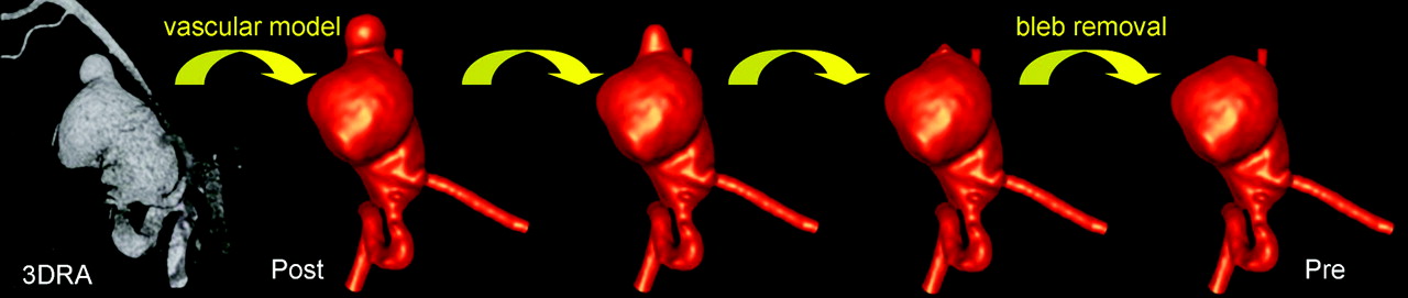
We created a second anatomic model for each patient by removing the bleb. This was achieved with application of a Laplacian smoothing to the bleb region manually delineated on the original anatomic model. Because a Laplacian smoothing procedure tends to shrink the surface being smoothed,12 fixing the boundaries of the bleb region (the neck of the bleb) and applying the Laplacian smoothing iteratively effectively smoothes out the bleb while preserving a smooth surface at all times. The procedure is illustrated in Fig 1. This figure shows the progressive smoothing out of the bleb of an aneurysm of the internal carotid artery. The final model without the bleb was considered to represent the stage of the aneurysm evolution just before the formation of the bleb. In what follows, this model is denoted “prebleb formation,” whereas the original model harboring the bleb is denoted “postbleb formation.” A new volumetric grid with the same resolution and element size distribution was generated for the prebleb formation model.

Vascular models of an aneurysm before (pre) and after (post) bleb formation created from 3DRA image.
Hemodynamics Models
Two CFD simulations were carried out for each patient, corresponding to the pre- and postbleb formation anatomic models. Blood was modeled as an incompressible and Newtonian fluid with attenuation ρ = 1.0 g/cm3 and viscosity μ = 0.04 Poise. The governing equations were the unsteady Navier-Stokes equations in 3D.17 Vessel walls were assumed rigid, and no slip boundary conditions were applied at the walls. Pulsatile flow conditions derived from PCMR measurement in healthy subjects were imposed at the inlet of the models. Flow waveforms were scaled with the inlet area to achieve a mean WSS of 15 dyne/cm2 at the inflow boundary of each model. This choice is consistent with studies relating vessel area and flow rates in internal carotid and vertebral arteries,18 as well as with the principle of minimal work expressed by Murray's law.19 Fully developed pulsatile velocity profiles were prescribed with use of the Womersley solution.20,21 Assuming that all of the distal vascular beds have similar total resistance to flow, traction-free boundary conditions with the same pressure level were applied at outlet boundaries. The same boundary conditions were applied to both the prebleb and postbleb formation models of each patient. The Navier-Stokes equations were numerically integrated by using a fully implicit finite-element formulation that allows arbitrary time-step sizes.8 We computed 2 cardiac cycles using 100 time-steps per cycle, and all of the results reported correspond to the second cardiac cycle. We then visualized the intra-aneurysmal flow patterns by using instantaneous streamlines colored according to the flow velocity magnitude. Maps of WSS magnitude were created to visualize the distribution of shear forces on the aneurysm wall.
Data Analysis
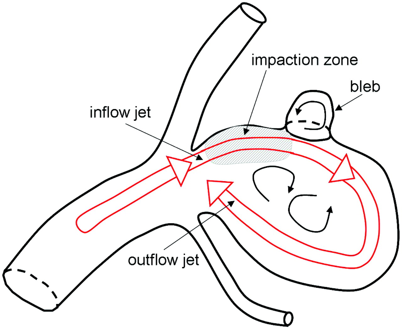
The results of the CFD simulations corresponding to the prebleb and postbleb formation models of each aneurysm were visually inspected, and the blebs were characterized according to the following characteristics (Fig 2): 1) bleb location with respect to inflow impaction zone (coincident, adjacent or away); 2) bleb location with respect to region of highest aneurysm WSS (coincident, adjacent or away); 3) maximal WSS in the bleb region before formation (high, medium, low); 4) maximal WSS in the bleb region after formation [high (> 1 SD), medium, low (< 1 SD) with respect to the mean WSS with the aneurysm]; 5) bleb alignment with inflow or outflow jet (aligned with jet, adjacent to jet, away from jet); and 6) maximal aneurysm WSS with respect to the spatial average of WSS in the last centimeter of the afferent parent artery (higher, similar, lower). To investigate whether blebs form in relationship to the aneurysm flow structures, we tested the following hypothesis. If blebs were unrelated to elevated WSS or some other flow-related mechanism, then we would expect either a random distribution of the blebs or, in the case of a low WSS mechanism, a distribution favoring sites away from the flow structures. The bleb distributions found were statistically compared with the expected random distribution of the mean surface area of the regions examined (impact zone, regions of elevated WSS). Whether the percent blebs adjacent to highest WSS differed from the percent blebs elsewhere is an inference regarding binomial proportions, and the null hypothesis is that there is no “location” difference in the percent blebs. Therefore, we used a simple z-test to assess statistical differences. The region “adjacent” was defined as the surface within 0.5 radius of the region in question. We performed all statistical analyses using SAS software (v9.2; SAS Institute, Cary, North Carolina).

Aneurysm and bleb characterization.
Results
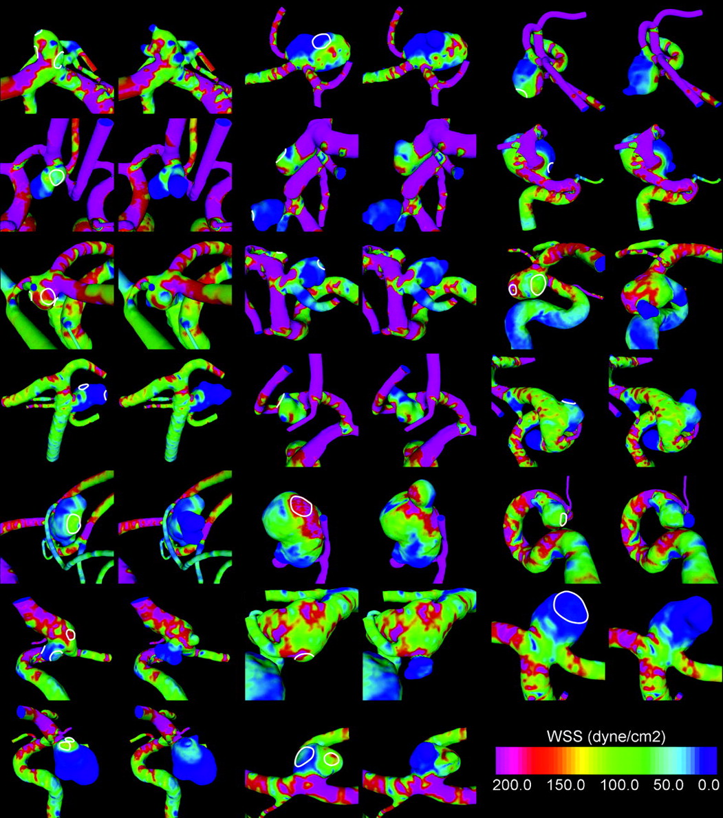
Visualizations of the WSS at peak systole are presented in Fig 3 for each aneurysm before and after bleb formation. It was observed that 90% of the aneurysms had maximal WSS higher (35%) or similar (50%) to the WSS in the parent artery. Only 10% of the aneurysms had WSS values uniformly lower than the parent artery. Average percentage area under high WSS was 22% (SD, 18%; minimum, 1.4%; maximum, 75%), and average percentage area of impaction was 18% (SD, 15%; minimum, 1.4%; maxium, 66%). Figure 4 shows the WSS distribution in an aneurysm with maximal WSS higher than the parent artery (top row) and another with WSS lower than the parent artery (middle row).

Visualizations of WSS distributions before (left) and after (right) bleb formation for all aneurysms in the sample. The regions where the blebs were smoothed out are indicated in the prebleb formation models.

Visualizations of WSS distributions before (left column) and after (right column) bleb formation in an aneurysm with WSS higher than the parent artery (top row), lower than the parent artery (middle row), and an example of the reduction of the WSS at the flow impaction zone when blebs are formed (bottom row).
It was found that 80% of the blebs occurred at or were adjacent to the region of the aneurysm with the highest WSS value determined on the prebleb formation model (P < .0001). A total of 20% of blebs were found away from this region. In addition, 60% of the blebs occurred at or adjacent to the flow impaction zone of the pre-formation model (P = .009), and 40% of blebs were found away from the impaction zone. Examples of aneurysms with blebs near the regions of highest WSS produced by the inflow jet impaction are shown in Fig 4.
A total of 83% of the blebs were found in a region of the pre-formation model subjected to WSS values higher (33%) or similar (50%) to the WSS of the parent artery (P < .0001). A total of 17% of the blebs occurred in a region of WSS lower than the parent artery. However, once the blebs were formed, 90% progressed to low WSS, and 10% preserved a high or medium WSS. It is interesting to note that blebs never progressed from a low WSS to either medium or high WSS. Blebs that had medium or high WSS after formation were always found in a region of high WSS before formation. Figure 4 (bottom row) shows an example of the reduction of the WSS at the flow impaction zone when blebs are formed.
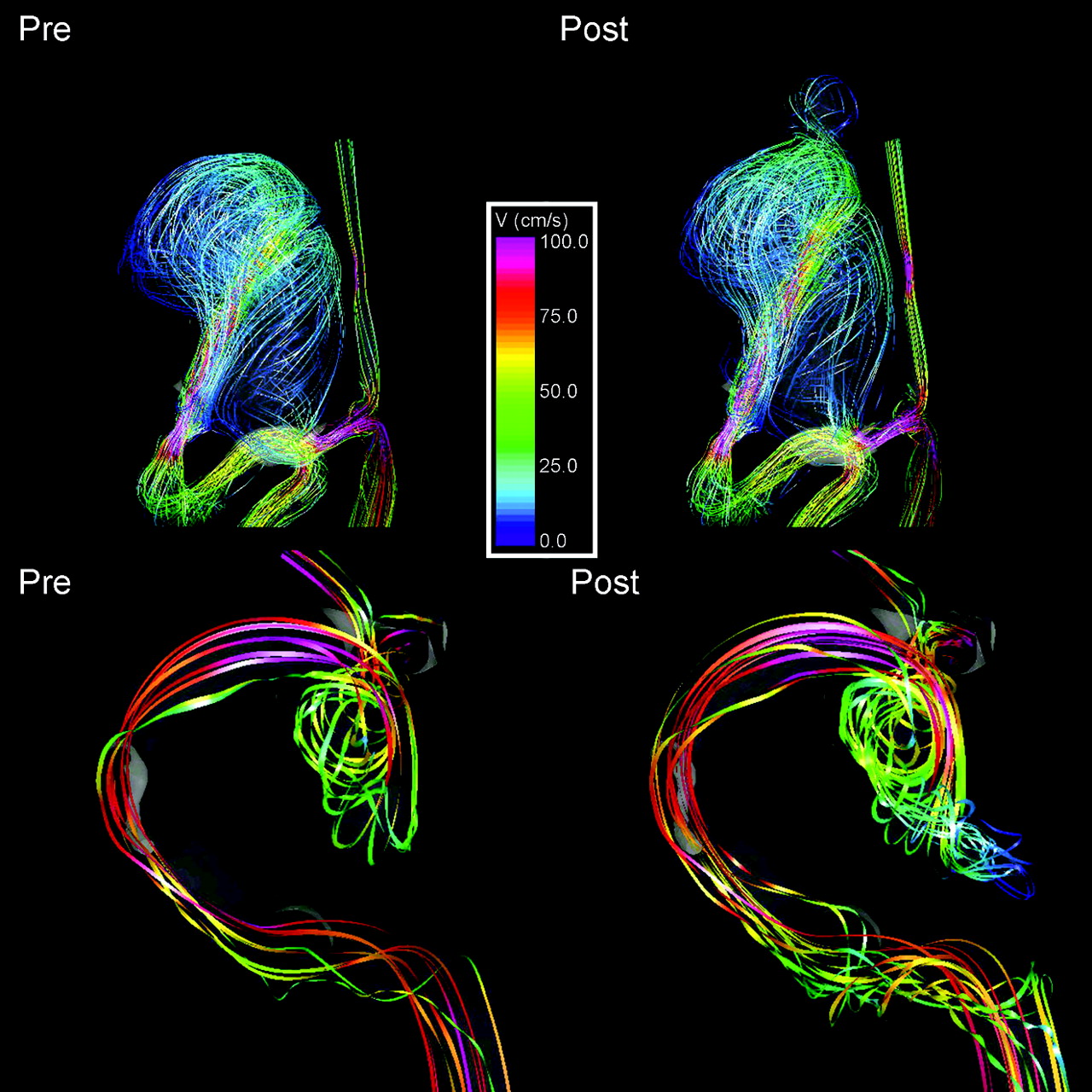
It was also found that 77% of blebs were aligned or adjacent to the inflow jet, whereas 17% were aligned with the outflow jet, and 6% were not aligned with the main flow direction (Fig 5). Finally, 60% of the blebs were found at the body of the aneurysm, whereas 27% were found at the dome, and 13% were found at the neck.

Visualizations of intra-aneurysmal flow structures before (left column) and after (right column) bleb formation. Top row: flow patterns showing the bleb at the flow impaction region. Bottom row: examples of an aneurysm with a bleb aligned with the inflow jet.
Discussion
Aneurysm blebs have been identified as a risk factor for increased risk for future rupture.2–4 The presence of multiple lobes or a daughter sac is more common in previously ruptured aneurysms than unruptured aneurysms.3 Therefore, recent studies have focused on these structures in an attempt to gain insight into the mechanisms of aneurysm development and rupture.7,22–24 Tateshima et al23 studied the intra-aneurysmal flow dynamics by using laser Doppler velocimetry in an acrylic basilar artery aneurysm model. By calculating the WSS distributing from fluid velocity measurements, they found the highest values of shear stress at or adjacent to the bleb of the aneurysm. This finding was later confirmed in a similar study with PCMR imaging24 where it was concluded that the elevation of WSS correlated with the natural history of rupture in cerebral aneurysms. In contrast, Shojima et al25 found that WSS was markedly lower in the dome and blebs in ruptured aneurysms and proposed that low WSS might be responsible for the fragility of the aneurysm wall that led to rupture. They also noted that the average WSS in the aneurysms studies was less than that of their associated parent arteries.
In our study group, the blebs were at or were adjacent to zones of elevated WSS in most cases. In addition, the blebs were, in most cases, aligned with the major flow structures and were not in zones of stagnation. These findings point to a correlation of flow structures with the formation of these structures rather than to the stagnation of flow. Once the bleb forms, the WSS in the bleb and the primary aneurysm sac is reduced as a result of the expansion of the wall and the formation of new flow recirculation regions inside the blebs opposing the main flow direction in the aneurysm. It is presumed that the final shape of the aneurysm is determined by the interaction of a flow-induced wall injury, the biomechanical response of the wall, and the interaction with extravascular structures of the perianeurysmal environment.22
Although most of the blebs were found related to either zones of elevated WSS or in alignment with flow structures, a few cases of bleb formation were not. Our data do not allow us to determine why this is the case; however, there are a number of possible explanations for this. First, our approach is based on the assumption that the main aneurysmal sac remains static with bleb formation. A significant change in the main sac morphology could lead to the relative displacement of the daughter sac at the time of formation in a few cases, or over time growth of the aneurysmal wall could cause a relative displacement bleb in relationship to the flow structures. Any change in the main sac structure introduces the possibility of significant influences of the perianeurysmal environment or other unknown factors. Second, our study assumes that the initiating damage that causes bleb formation is related to hemodynamic factors, in particular some effect of WSS. This may not be the only mechanism responsible for wall damage leading to blebs. Some other mechanism related to other factors of hemodynamics, wall biology, inflammation, or wall biomechanics unrelated to the major flow structures could be responsible for the bleb formation in these few cases.
We only considered aneurysms with blebs, and most of the aneurysms studied had WSS values larger than or similar to the WSS in the parent artery. Again, this finding suggests that perhaps the blebs were formed because of these relatively elevated WSS values. However, this hypothesis needs to be tested by comparing the relative WSS values between aneurysms with and without blebs. If this is confirmed, the relative WSS value could be used to identify aneurysms at higher risk for the development of blebs, which in turn has been associated with a higher risk for rupture.26
In this study, 2 models of an aneurysm containing a bleb or daughter sac were constructed from digital subtraction angiography rotational angiographic images. The first was the current state of the anatomy containing the bleb and the second was with the bleb removed. Our study assumes that the process of forming the final aneurysmal anatomy occurs in stages and therefore we considered the model with the bleb removed to approximate the prebleb state. From a logical standpoint, the primary lobulation forms first, and then a second lobulation is induced by biomechanical processes within the aneurysm wall. Although few aneurysms have been followed through the course of their developmental process, several reports have supported that this phenomenon does occur in at least a subset of aneurysms.4,5 The assumption that the primary lobulation morphologic feature does not change significantly with the development of a daughter sac, however, has not been as well documented. The few aneurysms reported with the development of a daughter sac and the few aneurysms Tateshima et al27 have observed have not shown dramatic changes in the primary aneurysm morphology. However, a modest but significant change in the configuration in the dome could occur with the structural alterations in daughter sac formation. In these cases, the aneurysmal orifice and orientation to the parent artery are preserved, and therefore, the major flow structures within the aneurysmal sac would be little changed, but the distribution of the regions of abnormal WSS could change. Despite our argument, the staged formation of the aneurysm is an assumption that needs to be confirmed with longitudinal studies.
Our study had several limitations. As in any simulation-based study, several approximations were made. The blood flow was assumed Newtonian, the vascular walls were assumed rigid, and physiologic pulsatile flow conditions from healthy subjects were used. Previous sensitivity analyses indicated that these assumptions do not significantly affect the main hemodynamic characteristics of cerebral aneurysms and can be considered second-order effects.8,28 The most important factor (ie, first-order effect) for a reliable characterization of the aneurysm hemodynamics is the geometry. In this study, the geometric models were constructed from 3DRA images, which provide the highest image resolution and contrast between the arteries and the surrounding tissues.
Conclusions
Aneurysm blebs are associated with the major high-flow structures within aneurysms and the associated regions of elevated WSS. Formation of an aneurysmal bleb leads to an overall reduction of WSS within an aneurysm because of the addition of an interfering zone of flow recirculation. These findings support the hypothesis that focalized damage of the aneurysm wall produced by locally elevated WSS induced by the blood flow can result in the development of blebs or irregularities in the aneurysm, which have been identified as rupture risk factors.
Footnotes
Philips Medical Systems and the American Heart Association (Grant No. 0655413U) and the National Institutes of Health (Grant No. 5R01NS059063) provided financial support.
Indicates open access to non-subscribers at www.ajnr.org
References
- Received January 21, 2009.
- Accepted after revision July 15, 2009.
- Copyright © American Society of Neuroradiology
In this issue


Jump to section
Related Articles
Cited By...
- Radiomic profiling of high-risk aneurysms with blebs: an exploratory study
- Intracranial aneurysm wall displacement depicted by amplified Flow predicts growth
- Evaluation of predictive models of aneurysm focal growth and bleb development using machine learning techniques
- Evaluation of predictive models of aneurysm focal growth and bleb development using machine learning techniques
- Prediction of bleb formation in intracranial aneurysms using machine learning models based on aneurysm hemodynamics, geometry, location, and patient population
- Intracranial Aneurysm Wall Displacement Predicts Instability
- Hemodynamics in aneurysm blebs with different wall characteristics
- Blebs in intracranial aneurysms: prevalence and general characteristics
- Towards the Clinical utility of CFD for assessment of intracranial aneurysm rupture - a systematic review and novel parameter-ranking tool
- Critical role of angiographic acquisition modality and reconstruction on morphometric and haemodynamic analysis of intracranial aneurysms
- Inflow Jet Patterns of Unruptured Cerebral Aneurysms Based on the Flow Velocity in the Parent Artery: Evaluation Using 4D Flow MRI
- Analysis of hemodynamics and wall mechanics at sites of cerebral aneurysm rupture
- Parent Artery Curvature Influences Inflow Zone Location of Unruptured Sidewall Internal Carotid Artery Aneurysms
- CFD: Computational Fluid Dynamics or Confounding Factor Dissemination? The Role of Hemodynamics in Intracranial Aneurysm Rupture Risk Assessment
- Generalized versus Patient-Specific Inflow Boundary Conditions in Computational Fluid Dynamics Simulations of Cerebral Aneurysmal Hemodynamics
- Wall shear stress association with rupture status in volume matched sidewall aneurysms
- Role of Fluid Dynamics and Inflammation in Intracranial Aneurysm Formation
- Quantification of speed-up and accuracy of multi-CPU computational flow dynamics simulations of hemodynamics in a posterior communicating artery aneurysm of complex geometry
- Effect of Bifurcation Angle Configuration and Ratio of Daughter Diameters on Hemodynamics of Bifurcation Aneurysms
- Hemodynamics of Cerebral Aneurysm Initiation: The Role of Wall Shear Stress and Spatial Wall Shear Stress Gradient