
Graphical Abstract

Abstract
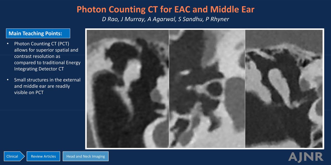
SUMMARY: Photon-counting CT (PCT) allows for improved spatial and contrast resolution compared with traditional energy-integrating detector CT. PCT offers markedly improved visualization of previously described structures, as well as those that were previously beyond the resolution of imaging. Although the anatomic details of the external ear and middle ear structures have been described previously, the rich detail of these structures has not been comprehensively reviewed in the radiology literature. The microarchitecture of the middle ear ossicles and bony protuberances are particularly well visualized on PCT. This review updates the existing literature with a detailed anatomic review of the external ear and the middle ear on temporal bone CT.
ABBREVIATIONS:
- EAC
- external auditory canal
- EID
- energy-integrating detector
- PCT
- photon-counting CT
- TMJ
- temporomandibular joint
Recent developments in photon-counting CT (PCT) have improved spatial and contrast resolution as compared with traditional energy-integrating detector (EID) CT scanners. PCT is particularly useful in imaging of the temporal bone because the anatomic structures are very small and complex. Though temporal bone anatomy has been described previously, PCT allows improved resolution and visualization of structures that are beyond the resolution of conventional EID scanners. This review serves as an update to the existing literature by illustrating the external and middle ear anatomy with PCT images.
REVIEW OF PCT PHYSICS
The superiority of PCT to EID CT is based on differences in the way each system converts x-ray photons into electrical signal. Conventional EID CT systems use a scintillator to convert x-rays into visible light, which are then converted into electrical signal by a photodiode. EID CT must use reflective septa in between the detector elements to reduce optical cross-talk, however these result in decreased dose efficiency, limiting spatial resolution. With EID CT, electrical signal from a single detector is proportional to the sum of the energy of all the photons that contact the scintillator. The energy level from all the x-rays that reach the detector are integrated to create an image. Greater weight is given to photons with higher energy levels, which is not ideal given the K-edge of iodine is 33.2 keV and optimal soft contrast is obtained with lower-energy photons.1
In comparison, PCT uses a semiconductor material that converts the energy from each x-ray photon directly into electronic signal. The signal created by a photon is proportional to the energy of the photon. Very low-energy signal from electronic noise is rejected in PCT, thus increasing SNR in comparison to EID, which includes electronic noise.2 Equal energy contribution from low- and high-energy photons leads to improved soft tissue contrast and increased signal from iodinated contrast. The ability to measure the energy of each photon contacting the detector allows for spectral imaging, similar to dual-energy CT. This can be used to produce virtual monochromatic reconstructions over a wide range of energies, material decomposition, iodine maps, and virtual noncontrast reconstructions. This allows for improved resolution of iodine-based contrast agents and decreased artifacts from beam hardening related to metal or attenuated bone. The technical details and advantages of PCT versus EID have been described previously.1 Ultra-high-resolution imaging afforded by PCT allows for greater detail of many submillimeter structures routinely encountered in temporal bone imaging.3,4 There is superior in-plane resolution and thinner section thickness with PCT in comparison with EID CT. The improved resolution allows for “crisper” images that routinely demonstrate fine detail. In particular, the microarchitecture of the ossicles, ossicular ligaments, tendons, and bony protuberances important for proper interpretation are all better visualized on PCT. All images contained in this review were acquired on a NAEOTOM Alpha PCT scanner (Siemens) at 0.2 mm section thickness.
IMAGE REVIEW OF ANATOMY
External Ear
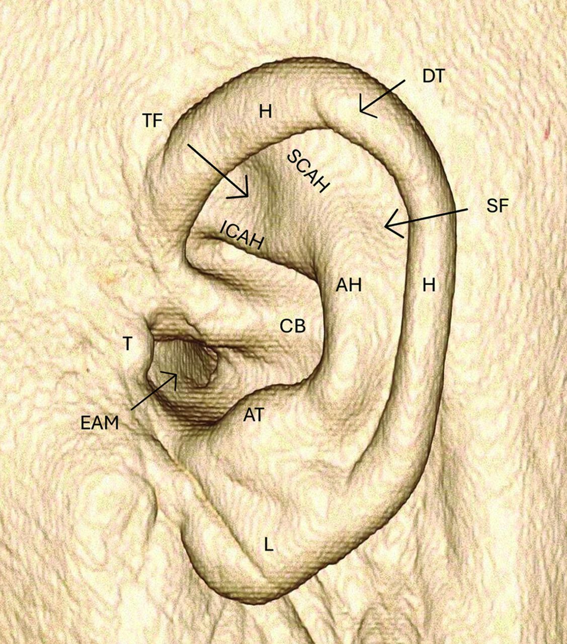
The external ear structure is composed of elastic cartilage and is covered by skin. The helix is the convex outer border of the external ear curving posterior and superiorly. The helix is partially folded inward toward the inner surface of the external ear. Along the posterior helix a small cartilaginous projection can be variably present called “Darwin’s tubercle.”5 The antihelix is anterior to the helix, also convex and curves in the same direction as the helix but with a smaller arc. Superiorly, it divides into the superior and inferior crura. Between these 2 crura is the triangular fossa. In between the helix and the antihelix is the scaphoid fossa. The concha, or concha bowl, is the concave depression that directs sound waves toward the external auditory meatus. The external auditory meatus is the anterior most part of the concha and serves as the opening of the external auditory canal (EAC). The tragus is a posteriorly directed cartilaginous structure attached to the anterior margin of the concha. Inferior to the tragus lies the lobule, or earlobe. The antitragus lies posterior to the tragus (Fig 1).

3D VRT demonstrating the external ear anatomy. AH indicates antihelix; AT, antitragus; CB, concha bowl; DT, Darwin’s tubercle; EAM, external auditory meatus; H, helix; ICAH, inferior crus antihelix; L, lobule; SCAH, superior crus antihelix; SF, scaphoid fossa; T, tragus; TF, triangular fossa; VRT, volume-rendered technique.
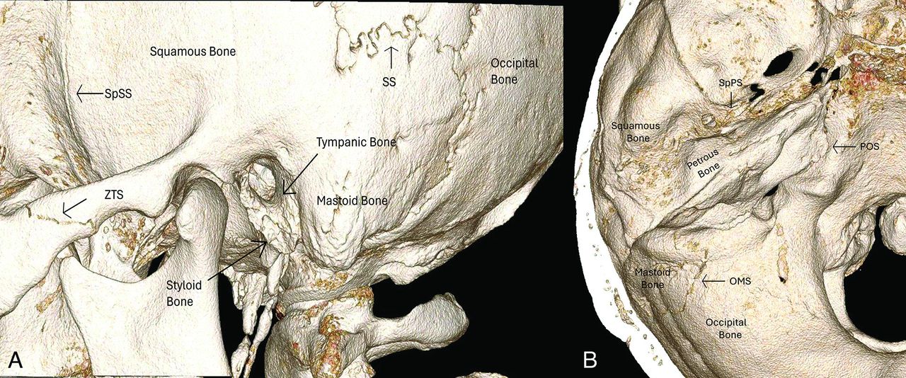
The temporal bones are at the sides and base of the skull and consist of 5 individual bones: squamous, mastoid, petrous, tympanic, and styloid (Fig 2A).6 The squamous bone forms the anterolateral and superior part of the temporal bone. Superiorly, the bone articulates with the parietal bone at the squamosal suture and anteriorly with the sphenoid bone at the sphenosquamosal suture. It serves as the lateral aspect of the middle cranial fossa and roof of the EAC. It also forms the glenoid fossa of the temporomandibular joint (TMJ).7 The squamous bone articulates anteriorly with the zygomatic bone at the zygomaticotemporal suture.

3D VRT image in lateral (A) and superior (B) projection. OMS indicates occipital mastoid suture; POS, petro-occipital suture; SpPS, sphenopetrosal suture; SpSS, sphenosquamosal suture; SS, squamosal suture; VRT, volume-rendered technique; ZTS, zygomaticotemporal suture.
The petrous bone is the most complex of all the bones forming the temporal bone superstructure (Fig 2B). It has a pyramidal shape with a wide lateral base and anteromedial apex. Anterolaterally, it articulates with the squamous bone at the petrosquamosal fissure. Anteriorly, it articulates with the sphenoid bone at the sphenopetrosal suture. Medially, the petrous bone articulates with the occipital bone at the petro-occipital suture. It forms the boundary of the middle and posterior cranial fossa.8 The petrous bone contains many structures discussed later herein, including the cochlea and vestibular systems, internal auditory canal, multiple fissures for perforating nerve branches, the tegmen tympani, and others.
The tympanic bone forms the posterior aspect of the TMJ glenoid fossa and the anterior wall, floor, and posteroinferior aspect of the bony EAC (Fig 2A). The petrotympanic fissure runs from the TMJ to the tympanic cavity and serves as the opening of the chorda tympani to exit the skull base anteriorly before joining the lingual nerve to provide gustatory sensation to the anterior two-thirds of the tongue. The tympanic sulcus serves as the attachment of the tympanic membrane. The mastoid bone is posterior and inferior to the squamous bone and immediately posterior to the tympanic bone. It articulates with the occipital bone posteriorly at the occipitomastoid suture. The styloid process projects downward and forward from the styloid bone. The stylohyoid ligament and stylohyoid, stylopharyngeus, and styloglossus muscles attach to the styloid process.9
The EAC consists of a hollow tube extending from the external auditory meatus to the tympanic membrane (Fig 3). The meatus serves as the opening to the canal. The canal is directed medially, anteriorly, and inferiorly relative to the meatus. The lateral one-third is cartilaginous, and the medial two-thirds is osseous and both parts are covered with squamous epithelial skin. The anterior wall, floor, and inferior portion of the posterior wall are formed by the tympanic bone, and the rest of the posterior wall and roof are formed by the squamous temporal bone.10 The fissures of Santorini are microscopic defects along the anterior portion of the cartilaginous EAC allowing for spread of tumor and/or infection between the anterior EAC at the preauricular soft tissues including the parotid gland.11 The foramen tympanicum, also known as the foramen of Huschke, is a small defect in the anterior wall of the osseous EAC that allows spread of tumor or infection into the posterior TMJ (Fig 3B). A potential pitfall is confusing this structure for a fracture or an erosion.

Coronal (A) and sagittal (B) images of the EAC. CEAC indicates cartilaginous external auditory canal; GF, glenoid fossa; FT, foramen tympanicum; MC, mandibular condyle; OEAC, osseous external auditory canal; PF, pars flaccida; PT, pars tensa; TA, tympanic annulus; TS, tympanic sulcus.
The tympanic membrane, the medial boundary of the EAC, is composed of thin fibrocartilaginous tissue. The thin pars flaccida is located superior to the thicker parts tensa. The tympanic annulus is the thickened ring of the membrane periphery that attaches to the tympanic sulcus in the bone. The fibrocartilaginous ring is incomplete superiorly and anteriorly, as is the osseous ring, forming a small gap called the notch of Rivinus. This makes the pars flaccida susceptible to perforation and spread of cholesteatoma.9
Middle Ear
The middle ear cavity is an air-filled space between the EAC and the inner ear. The lateral extent is the tympanic membrane. The superior border is the tegmen tympani. The inferior border is the jugular wall, which separates the middle ear from the jugular fossa. The anterior border is made of the carotid wall and the posterior border is the mastoid wall. The medial wall is the otic capsule. The tympanic cavity is further divided into the epitympanum, which is the part of the middle ear cavity above the superior border of the tympanic membrane, mesotympanum, which is at the level of the tympanic membrane; and the hypotympanum, which is below the inferior border of the tympanic membrane. The middle ear cavity can be further subdivided into the protympanic and retrotympanic compartments that are anterior and posterior to the tympanic membrane, respectively.12
The tegmen tympani, the superior border of the epitympanum, is part of the petrous bone (Fig 4A). It is a thin osseous structure that separates the temporal bone from the middle cranial fossa. Laterally, it continues as the tegmen mastoideum. The lateral margin interdigitates with the squamous bone at the petrosquamous suture. The petrosquamous suture continues into the epitympanum as the Koerner septum and divides the petrous and squamous portion of the mastoid air cells.13 The Koerner septum is a useful landmark for determining if there is erosive pathology, because it is consistently present while the pneumatization of the mastoid air cells are highly variable.

Coronal (A) and axial (B) PCT images demonstrating the anatomy of the epitympanum: AAA indicates aditus ad antrum; AER, anterior epitympanic recess; C, cog; KS, Koerner septum; Lat MAC, lateral mastoid air cells; MA, mastoid antrum; Med MAC, medial mastoid air cells; PS, Prussak space; Sc, scutum; TeM, tegmen mastoideum; TeT, tegmen tympani; TM, tympanic membrane.
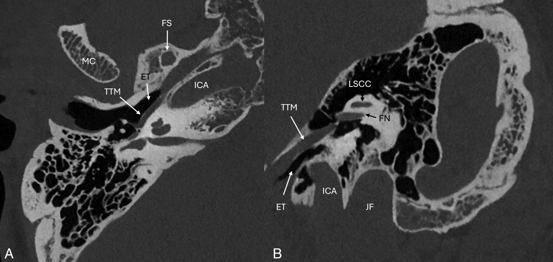
The anterior aspect of the epitympanum, also known as the anterior epitympanic or supratubal recess, is partitioned from the rest of the epitympanum by a thin bony septation called the “cog” (Fig 4B). The lateral epitympanic space is divided into the lateral epitympanic recess located superiorly and the Prusak space inferiorly. Laterally, the Prusak space is bordered by the scutum and pars flaccida of the tympanic membrane, medially by the malleus neck, superiorly by the lateral malleal ligament and inferiorly by the lateral process of the malleus.8 Superiorly, the epitympanum communicates with the mastoid air cells via the aditus ad antrum. The epitympanum also contains the incudal fossa, which contains the short process of the incus and the posterior incudal ligament. The hypotympanum is the smallest and most inferior part of the middle ear cavity, located below the mesotympanum (Fig 5). The middle ear floor is formed by the jugular plate, also called the fundus tympani. The floor contains the opening to the Eustachian tube and is bordered medially by the internal carotid artery.

Axial (A) and oblique (B) PCT images of the hypotympanum. ET indicates Eustachian tube; FS, foramen spinosum; ICA, internal carotid artery; MC, mandibular condyle; TTM, tensor tympani muscle.
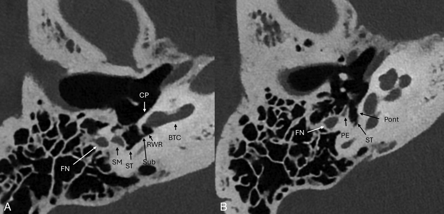
The mesotympanum (Fig 6) contains several important osseous protuberances and recesses. The cochlear promontory makes up most of the anteromedial wall of the tympanic cavity. The round window recess or niche is posterior and inferior to the promontory. Small ridges of bone project along the posterior medial wall of the mesotympanum superiorly (ponticulus) and inferiorly (subiculum) and form an osseous bridge between the sinus tympani and round window niche.14 The pyramidal eminence projects anteriorly from the posterior wall and contains the stapedius muscle within it. The sinus tympani is located medial to the pyramidal eminence. The facial nerve canal and facial recess are lateral to the pyramidal eminence. The oval window niche is a small depression posterior and superior to the cochlear promontory.

Axial PCT images (A and B) of the mesotympanum and retrotympanic structures. BTC indicates basal turn cochlea; CP, cochlear promontory; FN, facial nerve mastoid segment; RWR, round window recess; SM, stapedius muscle; ST, sinus tympani; Sub, subiculum; PE, pyramidal eminence; Pont, ponticulus.
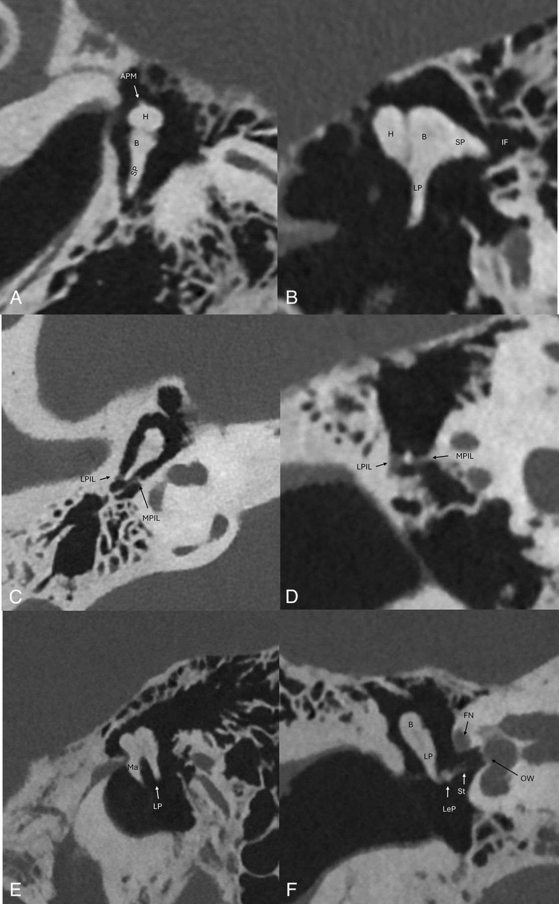
The mesotympanum and epitympanum contain most of the ossicular chain, which are composed of the malleus, incus, and stapes. The ossicular chain transmits sound from the tympanic membrane medially to the oval window. The malleus is made up of the head, neck, manubrium, anterior, and lateral processes (Fig 7). The manubrium, also known as the handle, is the longest process and attaches to the tympanic membrane. The tensor tympani muscle tendon, which dampens vibration, attaches to a small medially directed process on the manubrium.15 The lateral process attaches to the tympanic membrane just below the pars flaccida.16 The incus (Fig 8) is divided into 4 parts: the body, short process, long process, and lenticular process. The body of the incus articulates with the head of the malleus within the epitympanum at the incudomalleal joint forming the “ice cream cone” appearance on axial images. The short process of the incus projects posteriorly into the incudal fossa. The long process projects posteroinferiorly and parallel to the manubrium of the malleus creating the “molar tooth” appearance (Fig 8E).17 The long process curves medially into the rounded lenticular process, which articulates with the head of the stapes. The long process is often the earliest ossicle to erode in the setting of a pars flaccida cholesteatoma. The stapes (Fig 9) resembles a stirrup, consisting of the head or capitulum, the neck, 2 crura, and the base or footplate. The stapedius muscle tendon, which dampens vibration, attaches to the posterior aspect of the stapes neck.

Coronal oblique (A and C) and axial oblique (B and D) images of the malleus. AML indicates anterior malleal ligament; CFP, cochleariform process; H, head of malleus; I, incus; LML, lateral malleal ligament; LP, lateral process; M, manubrium attaching to the tympanic membrane; Ma, manubrium; N, neck of malleus; SML, superior malleal ligament; TTM, tensor tympani muscle; TTT, tensor tympani tendon.

Axial oblique (A), sagittal oblique (B and E), axial (C), and coronal oblique (D and F) PCT images of the middle ear cavity with anatomic details of the ossicular chain. Sagittal oblique image (E) depicts the “molar tooth” configuration of the malleus manubrium and long process of the incus in parallel. Axial oblique and axial images of the incudomalleolar joint depicts the classic “ice cream cone” configuration. APM indicates anterior process of malleus; B, body of incus; FN, facial nerve tympanic segment; H, head of malleus; IF, incudal fossa; LeP, lenticular process of incus; LP, long process of incus; LPIL, lateral band of posterior incudal ligament; MPIL, medial band of posterior incudal ligament; OW, oval window; SP, short process of incus; St, stapes.

Axial and axial oblique PCT images of the stapes. A, LeP indicates lenticular process of incus; SHN, stapes head and neck; StT, stapedius tendon. B, AC, anterior crus of stapes; PC, posterior crus of stapes; SC, stapes capitulum (head); SN, stapes neck; StT, stapedius tendon.
The ossicular chain is supported by the tensor tympani and stapedius muscles and ligaments specific to each ossicle (Figs 7 and 8). The tensor tympani muscle originates at the superior aspect of the Eustachian tube within the semicanal. The semicanal and the Eustachian tube run parallel to each other and are partially separated by the cochleariform process, which is a small bar of bone that extends laterally from the cochlear promontory. The tensor tympani tendon attaches to the posterior end of the cochleariform process and attaches to the neck of the malleus. The stapedius muscle is contained within a cavity within the pyramidal eminence. The tendon arises from a small hole in the apex of the pyramidal eminence and inserts to the neck of the stapes.
Each middle ear ossicle is supported by suspensory ligaments that provide passive support to aid in the conduction of sound through the middle ear to the oval window.18 There are 3 ligaments that support the malleus. The anterior ligament attaches to the malleal neck just above the anterior process and to the carotid wall next to the petrotympanic fissure. The superior ligament extends from the head of the malleus to the roof of the epitympanic recess. The lateral ligament extends from the malleal head to the posterior part of the notch of Rivinus. The incus is supported by the posterior incudal ligament, which has medial and lateral bands, and attaches to the posterior part of the short process to the posterior wall of the incudal fossa (Fig 8C, -D). The annular ligament of the stapes is a fibrous ring that attaches the footplate of the stapes to the margin of the oval window.
CONCLUSIONS
In this review, we highlight the technical differences between traditional EID CT and PCT scanners. Although many structures have been described by using traditional CT scanners, the ultra-high resolution afforded by PCT scanners allows for greater spatial resolution of these structures and visualization of structures that were once beyond the limits of EID CT. Future research should include evaluation of pathology by using this new technology.
Acknowledgments
The authors would like to thank Dr. Richard D. Beegle for reviewing the manuscript and images.
Footnotes
Disclosure forms provided by the authors are available with the full text and PDF of this article at www.ajnr.org.
References
- Received April 26, 2024.
- Accepted after revision May 24, 2024.
- © 2024 by American Journal of Neuroradiology


Jump to section
Related Articles
Cited By...
- No citing articles found.