
Abstract
SUMMARY: In this second of 3 review articles on the endovascular management of intracranial dural AVFs, we discuss transarterial treatment approaches. The treatment goal is to occlude the fistulous point, including the most distal portion of the arterial supply together with the most proximal portion of the draining vein (ie, the “foot” of the vein), which can be accomplished with liquid embolic agents via transarterial access. Anatomic factors to consider when assessing the safety and efficacy of a transarterial approach using liquid embolic agents include location, angioarchitecture, and proximity of arterial feeders to both the vasa nervosum of adjacent cranial nerves and the external carotid–internal carotid/vertebral artery anastomoses. Anatomic locations typically favorable for transarterial approaches include but are not limited to the transverse/sigmoid sinus, cerebral convexity, and superior sagittal sinus. In this review article, we discuss the technical approaches, outcomes, potential complications, and complication avoidance strategies for transarterial embolization.
ABBREVIATIONS:
- dAVF
- dural AVF
- EC-IC
- external carotid to internal carotid
- EVOH
- ethylene-vinyl alcohol copolymer
- TAE
- transarterial embolization
- TVE
- transvenous embolization
In this second of 3 review articles on the endovascular management of intracranial dural AVFs (dAVFs), we discuss transarterial treatment approaches.
Transarterial embolization (TAE) using glue or particles was the initial endovascular approach for intracranial dAVFs since the beginning of interventional neuroradiology in the 1970s.1 Glue embolization could achieve angiographic cure if the fistulous point was reached.1⇓-3 However, this was frequently not achievable due to limitations in obtaining distal penetration using glue, which polymerizes rapidly on contact with blood.4 In addition, cure via occlusion of the fistulous point using glue is more easily achieved when there is direct cortical venous drainage (Borden5 type III, Cognard6 type III–IV dAVFs) but is difficult when venous drainage is into the sinus (Borden I–II, Cognard I–II).7 Adhesion of the microcatheter resulting in removal difficulty is also a concerning limitation associated with glue.8 Similarly, particle embolization is limited by the inherent difficulty in controlling its distribution during injection as well as the temporary nature of the achieved occlusion with high rates of recanalization.8
The creation of ethylene-vinyl alcohol copolymer (EVOH) as a liquid embolic agent in 2005 allowed more controlled distal penetration of the liquid embolic, resulting in improved fistula occlusion rates, while reducing the risk of cranial nerve palsy or parenchymal arterial infarction.7,9,10 EVOH solidifies at a markedly slower rate than glue, forming a lava-like morphology that hardens during 20–30 minutes. This allows pauses during embolization, plug formation to allow later distal penetration, controlled reflux into adjacent feeders, and a greater ability to target embolization material toward the fistulous point.7,10 The distal penetration and diffusion of EVOH allows occlusion of multiple feeders from a single microcatheter position. Disadvantages include local inflammation, which can cause transient or, rarely, permanent cranial neuropathy when treating cavernous or hypoglossal canal dAVFs and increased porosity relative to glue, allowing dAVF recurrence.7⇓⇓-10
In addition, the creation of venous sinus occlusion balloons allowed greater rates of sinus preservation and angiographic cure when treating Borden/Cognard I–II dAVFs via an arterial approach.11 In this article, we discuss the treatment goals, favorable anatomic locations, technical approaches, outcomes, potential complications, and complication avoidance strategies for TAE using modern liquid embolic agents (EVOH).
Treatment Goal
TAE approaches to intracranial dAVFs aim to occlude the fistulous point and the foot of the draining vein via a distal artery position. Occlusion of arterial feeders without penetration of liquid embolic into the proximal portion of the draining vein is unlikely to achieve a permanent cure8 owing to the vast potential anastomotic network of dural branches that may provide supply to the shunt. Rather, proximal ligation of arterial feeders often induces new arterial feeders to the fistula that are more difficult to access from an endovascular approach, while blocking the initially accessible pathways.3 Similarly, proximal occlusion of an arterial feeder will not address the overall management goal when treating dAVFs, which is to prevent future hemorrhage or neurologic deficits arising from cortical venous reflux. While proximal occlusion can be used as a method of reducing intraoperative blood loss when planning microsurgical disconnection as the curative treatment,12,13 it is of little value when aiming for an endovascular cure.
Therefore, before embarking on TAE, the interventionist must judge the likelihood of achieving a suitable distal position with the microcatheter to allow an angiographic cure. Such a position must allow preservation of the vasa nervosum adjacent to cranial nerves and avoidance of external carotid to internal carotid (EC-IC) artery anastomoses (ie, the existence of a reasonable safety margin for EVOH arterial reflux).14 In the absence of these favorable factors, alternative treatment approaches such as transvenous embolization (TVE) or microsurgical disconnection should be considered.
Anatomic Locations
Anatomic locations of dAVFs that are typically suitable for TAE include the cerebral convexity, transverse sinus (combined with balloon sinus protection if the sinus is still used; Fig 1), lateral tentorial region, and superior sagittal sinus (with balloon sinus protection if the fistula is within the main venous compartment of the sinus). These locations are usually suitable for TAE due to the existence of a relative safe distance between the fistulous point and the cranial nerves or major EC-IC anastomoses, which lie predominantly over the ventral skull base.14 In addition, the dural arteries supplying AVFs in these locations (often partly supplied by relatively straight branches of the middle meningeal artery) allow easier technical access for a microcatheter.

Transarterial embolization of a transverse sinus AVF with sinus balloon protection. A, Anterior-posterior projection of a right ICA angiogram demonstrates a right transverse sinus dural AVF supplied by a recurrent meningeal artery (black arrow), which originates from the ophthalmic artery. It drains into the right transverse sinus (white arrow), where there is early venous filling. Sinus reflux is present (black border arrow). B, A detachable-tip microcatheter (SONIC; Balt) has been advanced through this artery, and its tip has been placed distally for a microcatheter DSA. The detachable segment is marked by the black arrow. The noninflated sinus-protection balloon (Copernic RC 10 × 80 mm; Balt) has been placed in the right transverse sinus and torcula (white arrow). C, Spot anterior-posterior film before embolization shows 2 microcatheters adjacent to each other for a modified pressure cooker technique. Arrows and labels indicate the proximal detachment point of the SONIC microcatheter, the distal tip of the flow-directed second microcatheter (Magic; Balt), the distal tip of the SONIC microcatheter, and the sinus-protection balloon (not yet inflated). D, Anterior-posterior subtracted fluoroscopic image demonstrates a glue-Lipiodol (Guerbet) mixture being injected from the distal tip of the second microcatheter (Magic) and forming a cast over the detachable segment of the SONIC microcatheter (pressure cooker technique). E, Spot anterior-posterior film demonstrates the inflated sinus-protection balloon, the glue cast, and an inverted-Y shaped early EVOH cast forming in the early stages of the embolization. F, Spot anterior-posterior film following completion of embolization and deflation of the balloon shows an extensive EVOH cast surrounding the fistulous point, forming a tunnel around the sinus, and extending into multiple adjacent arterial feeders (predominantly from occipital artery feeders).
Locations that may be suitable for TAE, either alone or in combination with TVE or microsurgical disconnection depending on angioarchitecture, include the petrous ridge (taking care to avoid seventh nerve palsy15) (Figs 2 and 3) and medial tentorial, ethmoidal, and falcotentorial junction dAVFs.16 Thus, most dorsal and lateral epidural locations can be considered for TAE.17

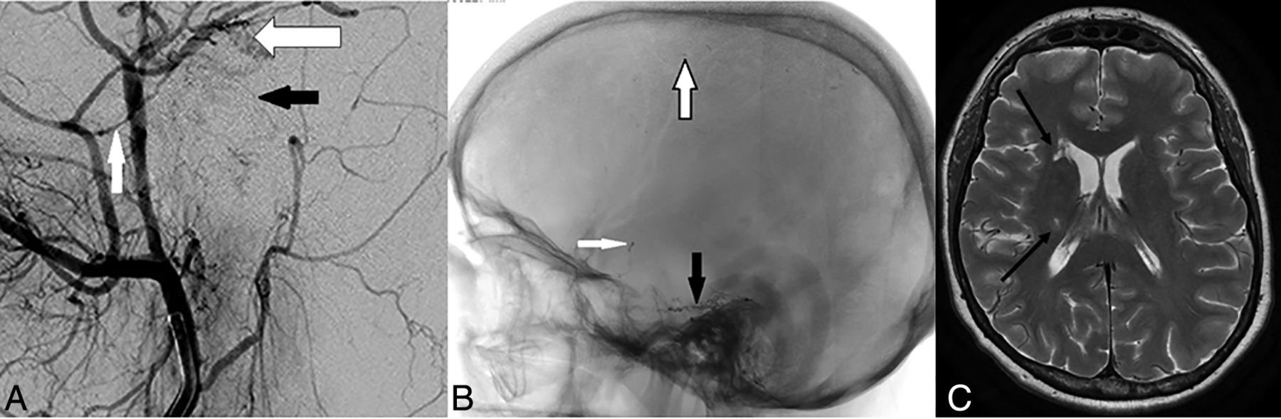
Transarterial glue embolization of a petrous dural AVF, complicated by brain parenchymal infarction. A, Lateral projection of an external carotid artery angiogram (magnified to show small vessels) demonstrates the petrous branch of the middle meningeal artery (white arrow) and the stylomastoid branch of the combined occipital/posterior auricular artery (black arrow) forming an anastomotic arch over the petrous temporal bone. This is the facial nerve arterial arcade and is the vasa nervosum to the geniculate ganglion and the intraosseous segments of the facial nerve. Adjacent to this is a complex focus of abnormal dural vessels (black border arrow) from a petrous dural AVF. Note the proximity of the AVF to the vasa nervosum. Thus, the more distal feeder of the middle meningeal artery was used for embolization. B, Following transarterial glue embolization, a spot lateral projection demonstrates a glue-Lipiodol cast filling the AVF (black arrow) but also droplets of glue in the intracranial ICA (white arrow) and distal cerebral convexity branches (black border arrow). These were due to transmission of glue across EC-IC anastomoses, most likely from middle meningeal artery branches into the lateral tentorial branch of the meningohypophyseal trunk. The patient woke with a temporary contralateral hemiparesis, which slowly resolved during several weeks. C, Axial TSE T2 image from follow-up MR imaging demonstrates small foci of gliosis in the right caudate head and posterior limb of the right internal capsule (black arrows), resulting from the prior embolic glue-related infarcts.

DSA and transarterial embolization using EVOH of a right-sided Borden III/Cognard IV petrous dural AVF. All images are in the lateral projection. A, Right external carotid artery injection demonstrates arterial supply to the AVF from the squamous temporal branch of the right middle meningeal artery (black-border arrow), from an enlarged petrous branch of the middle meningeal artery (white arrow), and from an enlarged stylomastoid artery (black arrow). Note the facial nerve arterial arcade formed by the latter 2 vessels. B, A microcatheter is present in the squamous branch of the middle meningeal artery (black-border arrow). Microcatheter-injection DSA from a distal point in the vessel demonstrates the fistulous point (white arrow) entering an ectatic petrosal varix. Note that the microcatheter tip is >20 mm from the origin of the petrous branch of the middle meningeal artery as seen in A, allowing reflux of EVOH back to the proximal marker and detachment of the 15-mm-length tip without penetration into the facial nerve arcade. C, Spot film following EVOH embolization via the squamous branch of the middle meningeal artery demonstrates the EVOH cast (black arrow) across the fistulous point and into the venous sac. The proximal marker of the detachable tip is visible (white arrow) and is well distal to the origin of the petrous branch of the middle meningeal artery as seen in A. D, Magnified right common carotid artery injection following embolization demonstrates the subtracted EVOH cast (black-border arrow) with no remnant filling the AVF. The petrous branch of the middle meningeal artery (white arrows) and the stylomastoid artery (black arrow) remains patent after treatment. The patient had preserved facial nerve function postprocedure. Reproduced - from Bhatia et al.15
Locations not typically suitable for TAE are the cavernous sinus and ventral aspect of the foramen magnum, corresponding to ventral epidural locations where cranial nerves traverse the skull base.17 TAE approaches to these locations pose a significant risk of cranial nerve palsy (III–VI for cavernous sinus, IX–XII for the foramen magnum14,18) or penetration across EC-IC anastomoses, resulting in parenchymal infarction.14 TAE approaches to these ventral epidural locations adjacent to the sphenoid bone and basiocciput should be avoided, and a TVE approach should be considered in the first instance.
Technical Approaches
When using EVOH for TAE treatments, there are 4 main technical approaches that can be used (and may be combined in some instances):
Plug formation
Pressure cooker (dual microcatheter)
Dual-lumen balloon
Balloon sinus protection.
The choice of technique is dependent on knowledge of the anatomic safety margins to the nearby vasa nervosum or EC-IC anastomoses, as well as the nature of the venous drainage (eg, balloon sinus protection for type I and II dAVFs). On the basis of this knowledge, the interventionist should set anatomic safety margins on the angiography monitor, beyond which they will not allow EVOH to travel.
When embolizing with EVOH, transmission of embolic material toward these margins should be managed by pausing embolization for 30 seconds to 2 minutes to allow solidification of the agent before recommencing.4,8 If reflux persists on recommencement, the pause period should be increased appropriately. This process of intermittent pausing will be repeated several times until the liquid embolic travels toward the desired target of the fistulous point.4,8
Technical Approaches: Plug Formation
Plug formation was the original technique used with the widespread release of EVOH for intracranial embolization8 and is still the most common technique. It relies on slow administration of EVOH via the microcatheter tip, often in slow, intermittent bursts for 5–10 minutes, until a plug of semi-solidified EVOH has formed around the tip, preventing further reflux of the agent.8,19 The process of intermittent pausing will be required to achieve a stable and reliable plug, as described above.
The technique is dependent on a degree of controlled reflux within anatomic constraints to form the plug.19 Once the plug is formed, further administration of EVOH will travel antegrade toward the fistulous point, allowing potential angiographic cure of the lesion. If a detachable-tip microcatheter is not used or the degree of reflux extends proximal to the detachable tip, the interventionist has approximately 20–30 minutes from the time of the first EVOH administration to complete the embolization (the time for the EVOH to completely solidify) to be readily able to remove the microcatheter.8 If the microcatheter cannot be removed due to adherence with the plug (ie, glued in), the microcatheter may be cut at the skin exit site and will incorporate into the vessel wall with time (though posing a risk of thromboembolic events) or can be removed with the aid of a snare using a modified monorail technique.20
The most significant predictor of the length of reflux required to form a stable plug is the diameter of the vessel. When the microcatheter tip is occlusive in the lumen (ie, a small diameter), the plug will form rapidly and the flow becomes antegrade soon after. Figure 3 demonstrates successful use of the plug-formation technique with a detachable-tip microcatheter in a small-caliber vessel.
If the lumen diameter is several times greater than the microcatheter (ie, a large diameter), a long segment of reflux will be required to create a reliable plug. In our opinion, when a large lumen diameter is present, use of a pressure cooker technique is advisable to avoid the excess time and reflux necessary to create a reliable plug. When there is a short anatomic safety margin, a pressure cooker or a dual-lumen balloon technique is also necessary to avoid reflux-related complications.15
Cerebral convexity dAVFs are often suitable candidates for plug formation as an embolization technique.19 We would hesitate to use branches of the occipital artery in the first instance as an embolization point for the plug formation technique, owing to their tortuous nature, invariable presence of transosseous small channels feeding the dAVF from the occipital artery that are difficult to cross, the presence of occipital-to-vertebral artery anastomoses, and the potential for reflux to the stylomastoid branch of the occipital/posterior auricular arteries, a branch that supplies the facial nerve.15
Technical Approaches: Pressure Cooker (Dual-Microcatheter) Technique
The pressure cooker technique was first described by Chapot et al,21 in 2014, for the treatment of brain arteriovenous malformations following the release of detachable-tip microcatheters. It has since been adapted for the treatment of dAVFs.22 This technique uses 2 microcatheters side-by-side and thus requires a guide or intermediate catheter large enough to accommodate both (usually a 6F system). One microcatheter has a detachable tip (commercially available in 15–50 mm lengths), while the second is usually a standard coiling microcatheter.21 In tortuous anatomy, standard coiling catheters can be difficult to navigate distally, and the use of lower profile coils via smaller microcatheters is an alternative option.23
Once the detachable-tip microcatheter has been positioned distally in the arterial feeder, the second microcatheter is advanced side-by-side so that it ends adjacent to the detachable segment of the first microcatheter. A plug of coils followed by glue for complete occlusion is formed with the second microcatheter so that the arterial feeder is occluded adjacent to the detachable segment and reflux will be minimized during embolization, resulting in forced antegrade flow (hence the name “pressure cooker”).21 A modified version of the technique using only glue and EVOH without the need for coils has also been described.22 The second microcatheter is then removed, and embolization of the dAVF is commenced using EVOH via the detachable-tip microcatheter.21 At the end of the procedure, the detachable tip is detached and the remainder of the microcatheter is removed, taking care not to dislodge the coil/glue plug that lies adjacent to it. An example of a modified pressure cooker technique (with balloon sinus protection) to embolize a transverse sinus Cognard IIa+b dAVF is demonstrated in Fig 1.
The major advantage of the pressure cooker technique is the ability to minimize reflux and allow antegrade flow of EVOH into the fistulous point.21,24 Thus, it is a useful technique when the anatomic safety margin is short or the lumen of the vessel is large (relative to the microcatheter).22 In addition, there is no time limit during embolization for more extensive malformations because reflux is minimized and there is little risk of “gluing in” the microcatheter. The major disadvantage is the additional time required to place a second microcatheter and form the coil/glue plug; in our experience, this additional time is largely offset by the time saved during embolization using this technique.
Technical Approaches: Dual-Lumen Balloon
Dual-lumen balloon microcatheters have 1 lumen for inflation of the balloon and a separate lumen for placement of a guidewire or administration of the embolic agent. With the balloon inflated, occlusion of the arterial feeder can be achieved allowing antegrade flow of EVOH toward the fistulous point via the second lumen while limiting reflux.25 Thus, this can also be considered a modification of the pressure cooker technique.
The advantages of a dual-lumen balloon are the same as those of a traditional pressure cooker technique, ie, maintained antegrade flow and limited reflux.25 In addition, the use of a single microcatheter in this technique can be undertaken through a smaller guiding system.26 Embolization and fluoroscopy times are markedly reduced.27 However, in our experience, the seal created by the balloon can be suboptimal. In addition, these dual-lumen balloon microcatheters do not track as easily in tortuous vessels. The recent release of low-profile dual-lumen balloons may help to overcome this limitation.28,29
Technical Approaches: Balloon Sinus Protection
In Borden/Cognard type I and II dAVFs, the venous drainage is directly into a dural venous sinus5,6 or an adjacent parasinus (common arterial collector) in the wall of the sinus.30 TAE of such dAVFs necessarily predisposes to embolic agent transmission into the dural venous sinus, leading to occlusion. There is also a risk of reflux back to the pulmonary circulation.31
In high-flow fistulas, occlusion of the fistulous point, which can be multiple, is difficult to achieve without occluding the sinus first (eg, with coils).31 If the dural sinus is needed to drain the brain, it is necessary to preserve this channel using dural venous sinus-protection balloons while treating the dAVF using TAE.32-34 Such preservation maintains the sinus lumen for future procedures if required as well as avoiding potential intracranial venous complications.34 This technique can be considered a reconstructive treatment approach, compared with the traditional deconstructive approach using transvenous coil occlusion.32,35
These sinus occlusion balloons (typically 8–10 mm in diameter) are placed via transvenous access into the relevant sinus and inflated so that they occlude the sinus.33 TAE with EVOH via one of the arterial feeders then allows occlusion of the fistulous point as well as controlled reflux into adjacent arterial feeders of relevance, resulting in an angiographic cure while preserving the sinus lumen.11,32,34 EVOH will line the external diameter of the balloon, creating a “tunnel” lined by EVOH with a patent lumen after the balloon is deflated and removed.32
A topical discussion point regarding these balloons is the duration of inflation. In our opinion, because the venous sinus of interest is responsible for draining a high-flow fistula and is in a venous hypertension environment, the normal venous drainage of the brain parenchyma is usually rerouted through other channels. This use of alternative drainage pathways is well-demonstrated on baseline angiography for high-grade dAVFs.3 As a result, there is no actual time limit to be followed. However, there is still the potential for thrombus formation within a segment of the venous sinus cranial/rostral to the balloon due to stagnation;35 thus, we often undertake temporary deflation every 10 minutes to prevent this complication.
The same sample case using a venous sinus-protection balloon in combination with a modified pressure cooker technique is demonstrated in Fig 1.
Outcomes from TAE
The largest published cohort of TAE for the treatment of intracranial dAVFs is from the Japanese Registry of Neuroendovascular Therapy, which reported clinical and angiographic outcomes from 858 TAE procedures.36 In this large cohort of patients, total occlusion was achieved in 26% of procedures, and subtotal occlusion, in a further 29% (combined 55%).36 However, this study incorporated a wide variety of embolic agents, including glue in 61% of cases and EVOH in only 13% of cases, with particles and/or coils used in 27% of cases; the choice of embolic agent evolved with time, resulting in a heterogeneous treatment sample.36 The lack of regulatory approval for EVOH use in Japan during much of the registry period limits the applicability of these results in the EVOH era.
The evolution of treatment strategies for intracranial dAVFs since the introduction of EVOH is well-described and has been associated with increased use of TAE as a sole approach, increased angiographic cure rates, and increased use of endovascular approaches for retreatment.10,37 Gross et al,37 in 2017, compared angiographic outcomes between 87 patients treated before and 173 patients treated in the EVOH era, demonstrating a significant increase in the use of TAE-only approaches (43% versus 61%), in cure rates via TAE-only approaches (23% versus 43%), and in cure via TAE treatment from a single arterial pedicle (11% versus 29%). The same study also stratified initial angiographic occlusion rates by AVF type, increasing from 63% to 75% for Cognard type I and from 57% to 76% for type II–IV AVFs after the introduction of EVOH.37 Transverse sinus AVFs (the most common anatomic subtype) resulted in occlusion rate improvement from 50% to 67%.37
Moenninghoff et al,38 in 2020, described outcomes from TAE using EVOH in 75 patients, reporting a complete occlusion rate of 77%, with 60% of cases cured after a single session. Our own results at Toronto Western Hospital in the EVOH era are similar (65.1% angiographic cure rate with TAE). Overall, these results indicate that TAE angiographic cure rates have increased significantly in the EVOH era to approximately two-thirds of cases.
Outcomes specific to each of the 4 TAE treatment approaches detailed above are described in smaller samples only, and the choice of approach is usually tailored to patient-specific angioarchitecture as well as the preferences of the interventionist. The use of TAE with EVOH in combination with balloon sinus occlusion for type I and II dAVFs is increasingly reported, most often for the treatment of transverse/sigmoid sinus dAVFs. Vollherbst et al,11 in 2018, reported complete angiographic occlusion of the dAVF in 86.4% when using balloon sinus occlusion in a series of 22 patients. Piechowiak et al,39 in 2017, reported angiographic occlusion in 8 of 9 patients with transverse/sigmoid sinus dAVFs treated via TAE with EVOH using a dual-lumen balloon with additional balloon venous sinus protection. These results, though limited by small sample sizes, suggest that the use of venous sinus balloon protection in combination with TAE using EVOH has a high angiographic cure rate for type I and II dAVFs.
Complications
The Japanese Registry of Neuroendovascular Therapy results from 858 TAE procedures describes an overall complication rate of 6.9%, with 30-day morbidity of 2.5% and mortality of 1.0%.36 The most common complications of TAE were arterial ischemic events (2.3%; with 1.3% distal thromboembolism, 1.0% arterial occlusion), vessel perforation (0.9%), venous occlusion with nonhemorrhagic deficits (0.6%), venous occlusion with hemorrhage (0.5%), vessel rupture (0.3%), and a nonretrievable microcatheter (ie, glued in [0.2%]). In this large cohort, complications related to TAE were more common during treatment of dAVFs involving the transverse/sigmoid sinus (8%), tentorium (including Petrous ridge, 12.4%), craniocervical junction (17.7%), and anterior cranial fossa (17.4%).36
These complication rates are consistent with our own experience at Toronto Western Hospital, in which 3 of 106 patients treated by TAE as the primary approach had an arterial infarct (2.8%) and 2 patients had periprocedural symptomatic intracranial hemorrhage (1.9%; subarachnoid, n = 1; intracerebral n = 1). No patients had cranial nerve palsy. Retrospective review of contributing factors in all 3 of our TAE cases complicated by arterial infarction identified penetration of embolic agents across EC-IC anastomoses into the cerebral parenchymal circulation as the underlying cause.
Avoiding Cranial Neuropathy during TAE: Anatomic Considerations
The absence of cranial neuropathy as a complication of TAE in our cohort at Toronto Western Hospital represents a concerted effort to preserve the vasa nervosum during TAE procedures. Detailed angiographic assessment of the dAVF is essential to identify the proximity of the vasa nervosum to the dAVF and its feeders. A detailed discussion of the arterial supply to the cranial nerves is beyond the scope of this article but is well-described in the literature.14,18,40
As a general principle, anatomic location of the dAVF in proximity to the sphenoid bone, basiocciput, or petrous temporal bone should alert the neuroradiologist to the potential risk of cranial neuropathy from TAE. This risk is because the major transit points of the cranial nerves through the skull base are across these osseous structures, and their vasa nervosum lie in proximity to these foramina.14 The ventral anatomic locations that are relative contraindications for TAE include cavernous, ventral foramen magnum, and, to a lesser extent, ethmoid and petrous dAVFs.
Cavernous dAVFs (indirect types, Barrow types B–D)41 are frequently supplied by branches of the inferolateral trunk, meningohypophyseal trunk, cavernous and ophthalmic branches of the middle meningeal artery, vidian artery, and artery of the foramen rotundum, all of which can potentially provide arterial supply to cranial nerves III–VI.14,18 In addition, the cavernous and orbital regions represent major sites of EC-IC anastomoses.14 Similarly, ventral foramen magnum/condylar dAVFs are typically supplied by the jugular and hypoglossal branches of the neuromeningeal division of the ascending pharyngeal artery, also supplying nerves IX–XII.14,40 Thus, transarterial approaches to these locations should be strongly reconsidered, while transvenous approaches are well-established.36,42,43
Petrous dAVFs always receive at least partial supply from the facial nerve arterial arcade, an anastomotic arterial arch supplying the facial nerve and formed by the petrous branch of the middle meningeal artery and the stylomastoid branch of the posterior auricular/occipital artery (Figs 2A and 3A).15,44 In our experience, TAE can be attempted for petrous dAVFs when there is, at minimum, a 20-mm margin from the planned embolization point back to the facial nerve arterial arcade, to allow a detachable-tip microcatheter (minimum tip length, 15 mm) to be used while preserving the arcade (Fig 3).15 Ethmoid dAVFs pose a greater risk to the central retinal artery during TAE rather than actual cranial neuropathy; microsurgical disconnection is usually preferred, though transvenous approaches are increasingly popular.45
Avoiding Embolization of EC-IC Anastomoses: Anatomic Considerations
Major EC-IC anastomotic pathways are predominantly distributed within 3 regions of the skull base and have been extensively described by Geibprasert et al, 2009:14
Orbital: Anastomoses between branches of the middle meningeal artery/internal maxillary artery and the ophthalmic artery
Petrocavernous: Anastomoses between branches of the middle meningeal artery/internal maxillary artery and the branches of the cavernous segment of the ICA (inferolateral trunk, meningohypophyseal trunk)
Upper cervical: Anastomoses between the ascending pharyngeal, occipital, and deep/ascending cervical arteries and the odontoid, muscular, and posterior meningeal branches of the vertebral artery.
Knowledge of these anastomotic channels should be used during angiographic assessment and treatment-planning for dAVFs, to choose the appropriate approach (TAE, TVE, surgery).14 In our experience, n-BCA (glue) is more prone to inadvertently crossing EC-IC anastomoses than EVOH, in part due to the speed at which it must be administered as well as the reduced distal control associated with administration of glue (Fig 2).7
Particle Embolization
While the use of polyvinyl alcohol particles for embolization of dural AVFs is not typically curative and can be more difficult to control than EVOH,8 polyvinyl alcohol can still play a role for palliation of symptoms.3,46,47 In particular, palliation of intractable pulsatile tinnitus in patients with transverse-sigmoid dural AVFs can be achieved using polyvinyl alcohol when the endovascular cure has not been achieved by transarterial EVOH or transvenous coiling approaches.3,47 The choice of polyvinyl alcohol particle size is important, ideally 150–500 µm, and has been guided by experience with particle embolization for epistaxis.47,48 This finding is because small particles (<150 and particularly <50 µm) may penetrate across EC-IC anastomoses leading to blindness or ischemic stroke,14,48 and large particles (>500 µm) may cause proximal vessel occlusion without symptom improvement.48
CONCLUSIONS
TAE is a useful and effective treatment option for dorsal and lateral intracranial dAVFs. Anatomic knowledge of the vasa nervosum and EC-IC anastomoses is essential in avoiding complications during TAE procedures.
Footnotes
Disclosures: Kartik Bhatia: UNRELATED: Employment: University Health Network (Joint Department of Medical Imaging). Timo Krings: UNRELATED: Consultancy: Stryker, Penumbra, Medtronic, Cerenovus; Royalties: Thieme; Stock/Stock Options: Marblehead.
Indicates open access to non-subscribers at www.ajnr.org
References
- Received February 2, 2021.
- Accepted after revision July 3, 2021.
- © 2022 by American Journal of Neuroradiology


