
Abstract
BACKGROUND AND PURPOSE: Imaging of intracranial stents is constrained by resolution limits of current clinical imaging techniques providing insufficient visualization of deployment details and impeding its use for computational hemodynamic (CHD) simulations. The purpose of our study was to evaluate whether ultra-high-resolution MicroCT scans can illuminate detailed aspects of realistic in vitro stent deployment and serve as a reliable basis for CHD simulations of blood flow through self-expanding intracranial stents.
MATERIALS AND METHODS: A Neuroform Treo (NF) stent and an Enterprise (ENT) stent were deployed in identical straight polytetrafluoroethylene tubes filled with contrast agent. MicroCT scans were obtained at a spatial resolution of 14 μm and used for ultra-high-resolution 3D reconstructions. CHD simulations were performed, with particular emphasis on local flow behavior near the wall and struts. Flow differences between the geometrically different stents were studied.
RESULTS: MicroCT data revealed strut prolapse near the markers for the closed-cell design (ENT) stent and at some of the unconnected vertices of the open-cell design (NF) stent, which also showed some misalignments. CHD simulations showed that reverse wall shear stress occurred near some of the strut vertices and markers for the NF but only near the markers for the ENT.
CONCLUSIONS: This work demonstrates the feasibility of ultra-high-resolution MicroCT imaging in elucidating important details of intracranial stent deployment as a basis for accurate CHD simulations and in enabling a structural and hemodynamic study of realistically deployed stents with different geometry and design.
The use of small metallic stents for treatment of intracranial vascular diseases has significantly increased, particularly since the introduction of several self-expandable nitinol stents designed specifically for the use during “stent-assisted coiling” of intracranial aneurysms1–3 or, more recently, in the treatment of intracranial atherosclerotic stenoses.4, 5 Two main stent designs are currently used for treatment of intracranial vascular diseases: open-cell design (OCD) and closed-cell design (CCD).
Despite their low-profile, some of the self-expandable nitinol stents may be associated with acute stent thrombosis or in-stent stenosis in 5%–9%,6, 7 or up to 30%–40% of the patients, respectively.8 A single plausible cause or mechanism for in-stent stenosis after Neuroform stent (NF; Boston Scientific, Natick, Mass) placement is lacking so far7; however as in coronary arteries, the underlying pathophysiologic mechanisms of in-stent stenosis probably involve multiple biologic, pharmacologic, hemodynamic, and other factors. Adverse hemodynamics, believed to be major contributing factors in the development of coronary in-stent stenosis,9 may be strongly influenced by unfavorable or adverse stent mechanics, such as underdeployment and stent malapposition.10
Several studies have shown that geometric and mechanical properties of stents as well as the associated wall shear stresses (WSSs), stagnation regions, and dynamic pressures may have a direct impact on restenosis.11 Recent computational hemodynamic (CHD) studies on the effects of stents on arterial hemodynamics have generally used idealized mathematic modeling of the artery and superimposed stent.12–17 These simulations have provided some useful information about the local WSS behavior near the struts and cell centers as a function of strut dimensions, stent porosity, and flow rates. Although more detailed analysis of flow over stent struts has been undertaken by using 2D models,18 which have also been used to predict deposition rates for drug-eluting stents,19 the importance of 3D hemodynamic behavior near the struts and wall has recently been recognized.17, 20
In this article, we evaluated the use of 3D ultra-high-resolution MicroCT imaging (eXplore Locus SP; GE Healthcare, Milwaukee, Wis) of intracranial stents for assessment of deployment geometry and CHD simulations of local flow near struts, including realistic effects of malapposition, cell misalignment, and strut prolapse, which are known to occur during actual in vivo deployment.
Materials and Methods
Stent Deployment
The following 2 self-expanding intracranial stents were deployed inside a straight 4-mm diameter polytetrafluoroethylene (PTFE; W.L. Gore and Associates, Newark, Del) tube under fluoroscopy (Axiom Artis dBA; Siemens, Erlangen, Germany): 1) a 4.5 × 30 mm Neuroform2 Treo stent (Boston Scientific) in a 4-mm tube, (The NF stent has every third cell connected and has strut segments with a diameter of ∼70 μm. The use of the stents reported here was governed primarily by the restricted availability of samples during our laboratory testing.) 2) a 4.5 × 28 mm Enterprise stent (Cordis Neurovascular, Miami Lakes, Fla) in a 4-mm tube. The components of the stent are a series of straight strut segments (∼60-μm width), connected by hairpin loops at the vertices. One connector joins every pair of neighboring vertices.
3D Reconstruction of the Stent and Vessel Wall
Ultra-high-resolution 3D reconstructions were obtained by using a single-orbit, cone-beam MicroCT specimen scanner, eXplore Locus SP, with the following parameters: 88 kV, 85 mA, 3-second rotation time, 0.4° increment, a 0.02-mm aluminum filter, and 500 projections. After scanning, a modified Feldkamp cone-beam algorithm was used to automatically reconstruct the 2D projections into a 3D volume with an isotropic voxel size of 0.014 mm. The MicroCT system output consists of contiguous axial sections in DICOM format. To ensure a clear segregation between the tube wall and the lumen during image segmentation, we filled the tube with barium sulfate suspension solution (60% w/v, 41% w/w; E-Z-EM, Westbury, NY).
Stent and Vessel Wall Surface
The DICOM datasets consisting of 2110 axial MicroCT sections, obtained as described above, were processed with Amira (Zuse Institute, Berlin, Germany). Segmentation threshold values were chosen such that the resulting surface conformed to the stent and wall dimensions. The segmentation editor was used to segregate the voxels representing the stent struts, the inner wall, and the lumen. Some manual processing to correct noise artifacts was applied at the stent and wall boundary.
3D Mesh Generation and Computational Hemodynamic Modeling
A computational mesh for each case was generated by using Gambit software (Fluent, Lebanon, NH). Proximal and distal tubes were added to the stented segment to reduce computational artifacts and to ensure that the flow entering the stented region was fully developed. A uniformly fine mesh was generated along the vessel wall and stent struts. The ratio of the mesh size h to the strut diameter d, h/d ≤0.3, was within the resolution limits recommended by Stuhne and Steinman15 in their simulations of flow over an idealized stent model. The highest resolution simulation had 8,600,000 mesh cells for the NF and 9,800,000 for the Enterprise. The node spacing on the struts was varied by a factor of 0.5. Spatial mesh convergence was considered satisfactory when the root mean square error in the velocity field between 2 consecutive mesh sizes was <3%.
Blood was modeled as an incompressible Newtonian fluid with an attenuation, ρ = 1.06 g/cm3, and a viscosity, μ = 0.04 g/cm/s. The simulations were performed by using Fluent 6.3 software. A flow-rate boundary condition was applied to generate steady time-independent flow corresponding to peak systolic centerline velocity, U = 70 cm/s. An inlet segment was added upstream of the stented section to allow the flow to become fully developed and attain a parabolic velocity profile. For the outlet, a zero pressure boundary condition was imposed. The Reynolds number, based on proximal vessel diameter and peak centerline velocity, was 550. Normal systolic flow velocities in human cerebral arteries range from 40 to 60 cm/s.21
Results
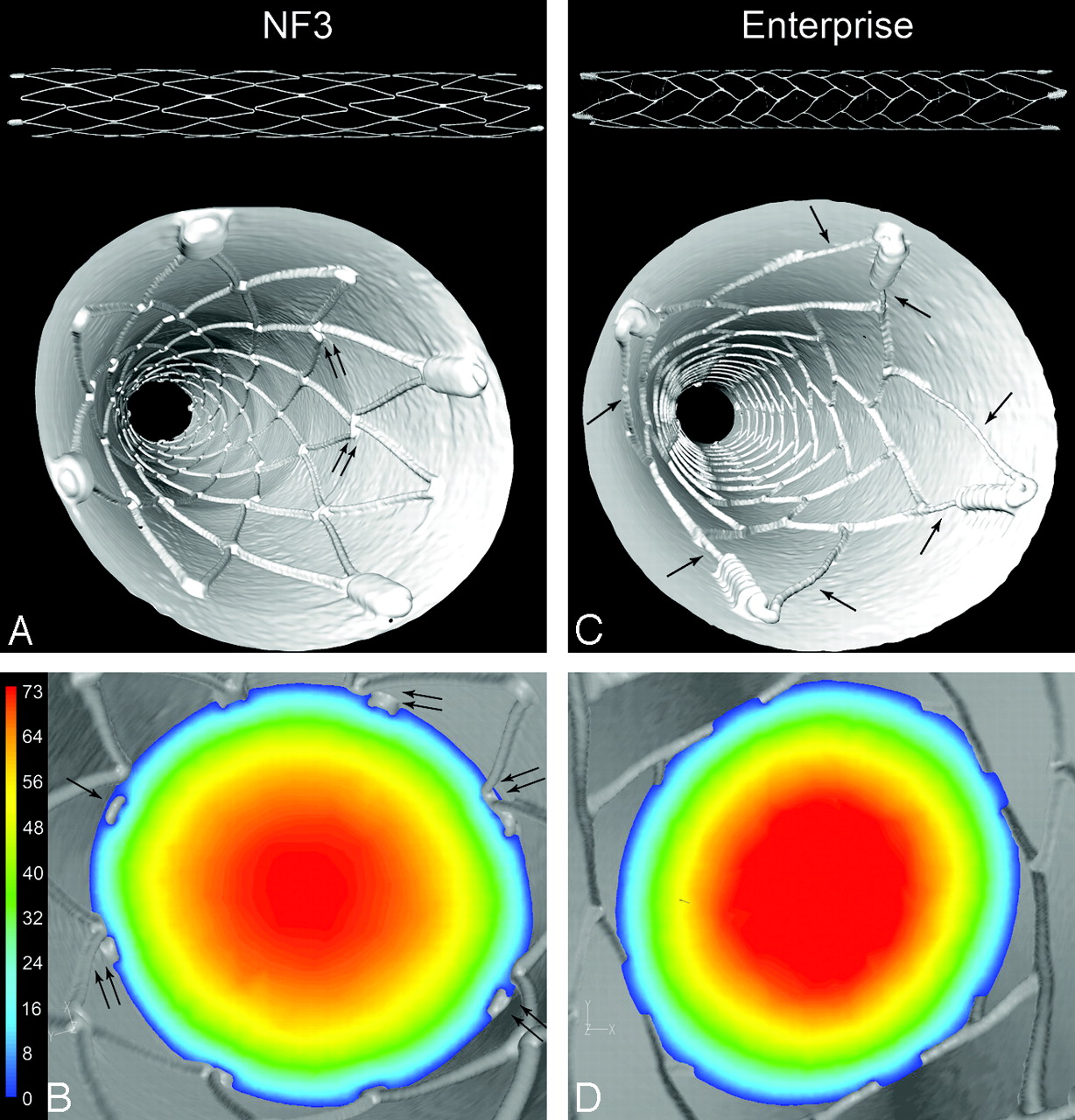
Stent surface reconstructions of the OCD NF stent and CCD Enterprise stent deployed inside the PTFE tubing had a slight elliptic cross-sectional contour, which also varied in degree of oblateness with the axial position (Table). The surface reconstructions of the stents (Fig 1A, -C, top) indicate the presence of vertex gaps in the NF stent (Fig 1A, top) and their absence in the Enterprise stent (Fig 1C, top). In the “down the barrel” views of the NF (Fig 1A) and Enterprise (Fig 1C), it was possible to see some slight misalignment and malapposition of the open vertices of the NF (foreground, Fig 1A) and prolapse of the struts carrying the markers of the Enterprise (double arrows, Fig 1C).

Stent surface reconstructions show the architecture of the OCD NF stent (top, A) and of the CCD Enterprise stent (top, C). Four platinum markers for improved visualization under fluoroscopy are attached at the ends of the stents. “Down the barrel” views of stent and wall reconstructions show the fully deployed NF (A) and Enterprise (C) stents inside PTFE tubes. Slight strut vertex misalignment is present along the NF stent (double arrows, A). Due to larger size markers, some struts are prolapsed into the lumen (arrows, C). Velocity (centimeter/second) contour plots on cross-sectional planes at peak systole are superimposed on the corresponding 3D reconstructions for NF (B) and Enterprise (D) stents. The struts and walls are shown in 3D projections (gray). The plane in B illustrates the flow near 8 vertices where strut vertex prolapse (arrow) and strut vertex misalignment (double arrows) are present. Low-speed flow under the prolapse and misalignment can be seen. Due to closed cell design, no strut prolapse is present with the Enterprise stent (D) except at the markers.
Stent dimensions after deployment*
Other differences among the stents as deployed in our in vitro samples were visible in “down the barrel” shots (Fig 1B, -D), showing the wall and stent (in gray) and a cross-sectional plane with a contour plot of the axial velocity magnitude. The NF (Fig 1B), though generally being well apposed to the wall over most of the stented segment, did exhibit small malapposition in several cells near the distal end of the stent. The prolapse of an open strut vertex into the lumen (Fig 1B) permitted some low-velocity flow between the strut and the wall. In addition, there was some misalignment of the vertices (Fig 1B). Because all vertices are physically connected, such a misalignment of vertices cannot occur with the Enterprise (Fig 1D), and thus no planes with strut prolapse into the lumen in the main body of the Enterprise were observed.
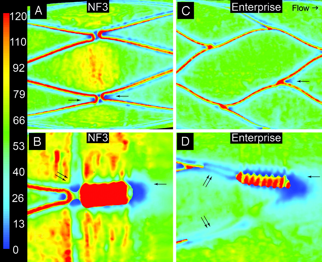
The WSS at systolic velocity in the stented regions is compared in Fig 2 by using the same scaling for both plots. The peak WSS at the centers of some of the NF cells was ∼85 dyne/cm2 compared with ∼68 dyne/cm2 for the Enterprise cells (Fig 2A, -B), whereas the average WSS over the cells was ∼56 dyne/cm2 and ∼47 dyne/cm2, respectively. Across the top luminal surface of the markers, the WSS values reached ∼280 dyne/cm2 for the NF stents and ∼200 dyne/cm2 for the Enterprise. Small zones of negative WSS were generated near some of the vertices of the NF stent (Fig 2C). Similar negative WSS zones were generated distal to the imaging end markers in both stents (Fig 2C, -D). Figures 3A, -C are magnified images of the WSS in typical interior regularly apposed cells in both the NF and Enterprise stents. Low, but not necessarily reverse, WSS zones developed near the strut vertices in both stents (Fig 3A, -C). The boundary layer flow is most strongly disrupted in both stents near the large diameter end markers (Fig 3B, -D). Larger zones of low WSS were generated both proximal and distal to the markers of both stents and also under the prolapsed Enterprise struts (Fig 3D, compare with Fig 1C).

Overall WSS (dyne/square centimeter) distributions at peak systole for NF (A) and Enterprise (B) along the tube show that the peak WSS is generated at the luminal face of the struts and markers. Increased WSS is seen at the center of the cells of the NF stent (A). The WSS pattern in the Enterprise case is relatively uniform along the tube (B). Contour plots of z-component (longitudinal flow direction) WSS are clipped to indicate locations of negative WSS for the NF (C) and Enterprise (D) stents. Negative WSS is present at some strut vertices (arrow, C) and the markers. For the Enterprise stent, negative WSS is present distal to the markers (arrows, D). Also, the struts connected to the markers prolapse into the lumen (double arrows, D).

WSS (dyne/square centimeter) distributions at peak systole for a regularly apposed cell for NF (A) and for Enterprise (C) stents. Low WSS regions develop upstream and/or downstream to strut vertices (arrows, A and C) and markers (single arrows, B and D). The location where the markers are connected to the struts is also subjected to low-velocity flow (double arrows, B and D). The prolapsed strut vertices (double arrows, D) permit low-speed flow between the strut and the wall, creating a low WSS shadow under the raised strut.
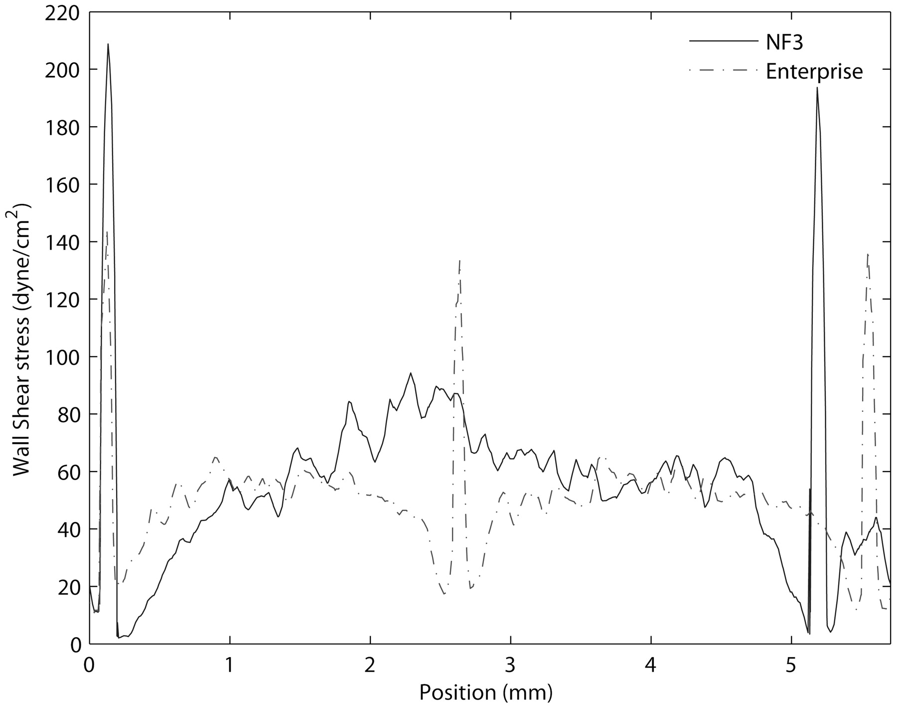
Hemodynamic differences between the fully apposed cells of the NF and Enterprise stents are also shown in Fig 4, which is a plot of the WSS along an axial line (in the flow direction) spanning approximately 2 cells of the Enterprise stent and an equivalent length and position for the NF stent. The 2 spikes in WSS near the origin correspond to the peak values in the WSS as the flow passes over the tops of the struts. Note that the peak value of the Enterprise (∼140 dyne/cm2) is less than that of the NF (∼200 dyne/cm2). The spike in the middle of the plot near z = 2.7 corresponds to the next strut on the Enterprise. The next strut downstream on the NF (which has cells nearly twice as long as the Enterprise at maximum extent) is at z = 5.2. Figure 5 shows near-wall (10 μm away) velocity vector plots for the same cells displayed in Fig 3B, -D. The velocity vectors are color-coded with velocity amplitude; differences in length are due to the projection of a 3D vector onto a 2D surface. Peak velocities of approximately 3 cm/s were reached principally near the tops of the struts and markers. The low speed flow, <∼1 cm/s, under the prolapsed struts connected to the Enterprise end markers (Figs 1C and 3D) is clearly apparent in Fig 5B.

Plot of WSS along a longitudinal line across a regularly apposed cell. The NF cell is longer than the Enterprise cell by about a factor of 2. High WSS is present on the luminal faces of the struts. WSS is low proximal and distal to the struts, whereas inside the cells, the WSS increases toward the middle. The average WSS for the NF stent is approximately 57 dyne/cm2, whereas for the Enterprise stent, it is approximately 46 dyne/cm2.

Plots of near-wall (10 μm) velocity vectors (centimeter/second) around imaging markers for the NF (A) and for the Enterprise (B) stent. Due to the size of the NF stent markers (∼180-μm height and 400-μm width), the flow is disturbed (A) in these regions. A similar perturbation occurs near the Enterprise markers (∼250-μm height and 350-μm width). The flared ends of the Enterprise stent keep the struts here away from the wall and permit near-wall flow under the strut (B), which does not occur with the NF (A).
Discussion
This work demonstrated the feasibility of ultra-high-resolution MicroCT datasets for visualization of architectural and structural details of 2 self-expanding intracranial stents. Two currently US Food and Drug Administration (FDA)-approved fundamentally different stent types were imaged after realistic deployment (not modeled) in an in vitro PTFE model: the OCD Neuroform and the CCD Enterprise stent. The 3D data obtained allowed accurate CHD simulations and calculations of WSS created by geometry, design, and deployment characteristics of each stent.
The visualization of small intracranial stents by using noninvasive imaging techniques such as multisection CT (MSCT, including a 64-section scanner) has significant limitations due to relatively low spatial resolution, blooming artifacts, and partial volume averaging.22, 23 Therefore, MSCT is currently insufficient for satisfactory assessment of stent deployment and conformability. High-resolution invasive imaging such as digital subtraction angiography is superior to MSCT but provides only 2D visualization without enough information to assess actual stent deployment. C-arm flat panel CT (FPCT) proved recently superior in the imaging of intracranial stents and in allowing visualization of deployment characteristics and detection of adverse stent mechanics.24–26 Although the high spatial resolution of a C-arm FPCT, reaching approximately 0.17-mm isotropic, is superior to 64-MSCT (0.3 × 0.3 × 0.4 mm),27 recent work has shown that it is not sufficient for accurate CHD studies.28 As shown in the present study, ultra-high-resolution MicroCT datasets providing a spatial resolution of 0.014 mm are not only capable of visualizing the main features of stent deployment but also reveal minute details such as malapposition, minimal strut prolapse, and cell misalignments undetectable with other imaging techniques. These highly accurate datasets were successfully used for assessing hemodynamic effects caused by stent geometry, strut dimensions, and deployment characteristics.
Due to variations in geometry, profile, and design, both stent types used in this work exhibited differences in deployment characteristics and their subsequent effects on hemodynamics. OCD stents such as NF provide greater mechanical flexibility with the potential to adjust their cell size to irregular and curved anatomy. This design has, on the other hand, the “drawback” that unconnected vertices may be more susceptible to adverse mechanics, such as strut prolapse, even in a simple straight vascular model (Fig 1A, -C). The conformability of both stents (OCD and CCD) in curved vessel segments has been shown to differ29, 30 but is not the subject of the present article. Asymmetries found with the NF stents may also appear in peripheral or coronary OCD stents. Therefore, we expect that some stent deployment features and observed hemodynamic behavior from this study will also apply to flow through stented vessels in vascular territories.
Because all vertices are connected, CCD stents do not exhibit cell misalignment, and thus only minimal strut prolapse was observed in our straight-vessel model. As has been demonstrated, a CCD stent such as the Enterprise may exhibit more significant adverse mechanics when placed in curved models, such as flattening (“ovalizing”) or kinking.29, 30 The CCD Enterprise in the present study exhibited a slight prolapse of the struts carrying the radiopaque markers (Fig 1C), which is intrinsic to its flared design at each end. In addition, the Enterprise design showed variation in the size of the stent cells over the length of the stent.
These small but real deviations from symmetry and uniformity seen in both stents deployed in straight regular tubes under ideal conditions would be very difficult to include accurately in a theoretic computer model, illustrating the importance of accurate realistic 3D reconstructions as used in the present study. Whether more significant adverse stent mechanics, as seen in curved anatomy, may cause deleterious effects is currently unclear and requires further investigation.
The importance of even minor asymmetries in stent deployment has been clearly demonstrated in vascular cross-sections from high-resolution histologic studies (LaDisa et al,13 Fig 7). Such small geometric anomalies are readily identifiable in comparable MicroCT cross-sections (Fig 1B, -D). Previous studies that have analyzed flow near the struts by using model stents11, 20, 31 have not included realistic strut prolapse. This, however, can permit flow between the strut and the wall (Fig 1B) and can significantly change the local WSS and modify the recirculation zones forming near the struts.
Although MicroCT has previously been used to image stented rabbit iliac arteries,13 the challenge of obtaining realistic 3D data of stents, sufficiently accurate for CHD simulations, has lead to the use of theoretic computational models instead. The present study is, to our knowledge, the first report on the use of MicroCT imaging of intracranial stents providing sufficiently (ultra) high-resolution 3D data of both the stent and the wall to make the use of modeling no longer necessary. Important realistic geometric details related to actual stent deployment, such as wall apposition and strut prolapse not represented by such models, become identifiable. These 3D data enable accurate hemodynamic studies in small intracranial stents including effects of adverse mechanics, which may allow assessment of the mechanical and hemodynamic performance of different stent types in the future. Such detailed description of flow characteristics is of potential major importance in assessing inhomogeneities and variations in drug diffusion of drug-eluting stents.32
A major focus of this study was on zones with small recirculation vortices and low or negative WSS near the struts. In addition to the potential physiologic importance of these zones, they are also useful in demonstrating the level of hemodynamic detail that can be obtained by using the MicroCT-based CHD approach proposed in this study. The basic hemodynamics for the well-apposed cells of the different stents were similar and were in good qualitative agreement with previous studies based on CHD simulations using idealized symmetric mathematically 3D modeled stent deployment.11–13, 33 Because the open cells of the NF stents are less constrained, the cell-to-cell variations due to natural deployment asymmetries can be dramatically greater (Fig 2A) than those predicted by the symmetric theoretic models.
The present study reinforces the importance of 3-dimensionality in the development of recirculation zones near the struts. Seo et al14 noted the formation of helical vortices distal to such struts, whereas He et al20 have studied a model of a curved strut and concluded that recirculation zones can be reduced by orienting struts as much as possible in the flow direction. In our simulations, recirculation zones were only observed near strut vertices or markers (Fig 2C, -D) at positions where the struts or markers had a perpendicular projection to the flow direction. This is consistent with the 3D strut model of Rajamohan et al17, though their larger recirculation zones may have been caused by the higher profile of their stents (400-μm diameter struts, with 200-μm projection into the lumen, compared with ∼60–80 μm for the NF and Enterprise).
Large recirculation zones were generated by both stents near their markers. The effect of the prolapsed Enterprise struts on the boundary layer flow can be seen in Fig 5B, where the blue vectors indicate low-speed flow between the struts and the wall. This important effect of flow underneath prolapsed struts disrupting recirculation zones and perturbing the flow downstream is likely caused by the flared ends of the stent and has not previously been described.
The NF stent appears to have its markers connected with the struts in a manner that permits the struts and markers to remain well apposed to the wall. We did not see any evidence of prolapse near the markers for this stent. A comparison of Fig 5A and B shows no evidence of flow under the struts connected to the marker for the NF stent. Nonetheless, the NF markers and struts generate recirculation zones both proximal and distal to the marker, whereas the Enterprise produces recirculation zones only on the downstream side of the strut junctions. Although the size of the markers is similar (∼180-μm height and ∼400-μm width for the NF compared with ∼250-μm height and ∼350-μm width for the Enterprise), the Enterprise markers have a more cylindric cross-sectional shape. For both stents, the effects of the struts on the main flow in the center of the lumen are relatively small.
Although the Enterprise struts carrying the radiopaque markers exhibited significant prolapse (Fig 1C), the stent showed no evidence of recirculation zones or WSS reversal within the middle segment cells, though zones of comparably low WSS were generated near the strut vertices (Fig 3C). The larger diameter NF struts showed small WSS reversal zones near some of the stent vertices (Fig 2A, -C). These zones were significantly more pronounced near the open NF cells, which exhibited some vertex prolapse and strut misalignments. It may be that the slightly larger NF struts are just above the threshold for the generation of these small recirculation zones at the Reynolds numbers used here. This possibility is consistent with the formation of larger recirculation zones in those cells of the NF stent in which the struts prolapse farther than normal into the lumen (Fig 2C) and with the formation of such recirculation zones in both stents distal to the much larger diameter markers (Fig 2C, -D).
The WSS distribution inside the stented region was in agreement with results from previous studies. Low WSS was present in the vicinity of struts and cell vertices, whereas increased WSS was located on the luminal face of the struts, which projects further into the higher velocity fluid stream away from the wall. The behavior of the WSS near the struts is similar in both stents and increases from near zero at the base of the strut to approximately 60 dyne/cm2 to 90 dyne/cm2 near the cell centers. The vessel wall area exposed to low (<5 dyne/cm2) WSS is considerably smaller for the Enterprise stent (0.08% ± 0.01) than for the NF (0.6% ± 0.1). This difference suggests that a lower profile stent (smaller strut dimension) may cause less potentially deleterious zones of low and oscillating WSS, which have been found to be associated with neointimal growth.9
By using the approach presented in this study, important knowledge and understanding of mechanical stent behavior and related mechanical-hemodynamic interactions can be gained. Their application in the evaluation of various stent geometries and designs may contribute to possible future improvements.34
Caveats
Considering the 2 types of stents being studied here, one must keep in mind that some observed differences may be due to the deployment procedure itself and that some of the observed (potentially deleterious) effects may be reduced or exaggerated in vivo. The aim of this study was not per se to determine superiority/inferiority of a specific stent type but rather to look for basic hemodynamic differences between 2 stent designs and to assess the effects of adverse mechanics, whether due to stent design or the inherent variability associated with deployment.
We evaluated stents deployed in a straight nonbiologic PTFE model, lacking true arterial wall compliance or physiologic response such as endothelialization. As demonstrated previously, the PTFE model has radiopacity and mechanical properties that allow artifact-free high-resolution CT. This novel type of in vitro stent imaging allows assessment of realistic deployment characteristics including adverse mechanics30, 35 and thus serves as a useful basis for initial studies of the hemodynamic implications of these effects. Small deviations from uniform circular cross-section were captured in both samples, but this ellipticity (Table) was minimal and, therefore, unlikely to affect the results presented here, as reported elsewhere.36
Time-dependent simulations were also performed for the 2 stent cases described here by using the standard Ku waveform, which has a Womersley number of 6.5 and does not exhibit regions of reversed flow.37 However, the key hemodynamic features described in this article for this waveform applied to our model (a straight tube) tended to vary principally only in amplitude over the pulsatile cycle, as observed in the simulations of Benard et al16 and Seo et al.14 Thus, we have used steady flow simulations in the present work. Time-dependent and transient effects can be significant under certain conditions and are the focus of further research.
Summary and Conclusions
The present study is, to the best of our knowledge, the first attempt to use MicroCT-based 3D data of sufficient spatial resolution to incorporate and accurately emulate irregularities inherent in the real physical stent deployment within a vascular model, which can then serve as a basis for accurate CHD simulations. We have studied 2 intracranial stent designs, currently approved by the FDA: the OCD NF and the CCD Enterprise stent. Although some results in this article are similar to those in previously published work on stent cells using a symmetric and uniform model, the changes in hemodynamics caused by asymmetric, malapposed, misaligned, or prolapsed stent elements are novel and show the potential importance of such adverse mechanics on critical parameters such as the WSS.
This study demonstrates an enhanced capability for evaluating in detail the hemodynamic consequences of specific stent designs and may become a means for directly comparing their effects in a realistically deployed state. Although the basic hemodynamics observed in the 2 stent types are similar, there were some differences of potential significance. The WSS within the regularly apposed cells was lower for the CCD stent than for the OCD stent. Throughout the main stent body, there were no recirculation zones or WSS reversal for the Enterprise, and there were some very small reversal zones for the NF, generated by cell misalignment and strut prolapse. Due to their larger dimensions, significant reversal zones were found near the stent markers.
As shown, by modeling blood flow through stents by using ultra-high-resolution 3D data, optimization of stent deployment and advancements in stent design may be possible and will help to minimize deleterious effects. Such improvements may include streamlining the shape of the struts and markers or modifying the shape and size of cells to minimize strut prolapse and vertex misalignment. Because OCDs and CCDs are also used in coronary interventions, stent geometry and symmetry affecting local hemodynamics will be important for optimizing drug release in eluting stents.
MicroCT-based CHD studies could become a powerful tool for investigating and refining current and future stent designs and have the potential to become an important component of benchmark testing of endovascular devices.
Footnotes
Portions of this work were supported by the Texas Learning and Computation Center at the University of Houston.
References
- Received July 17, 2008.
- Accepted after revision October 5, 2008.
- Copyright © American Society of Neuroradiology


