
Abstract
BACKGROUND AND PURPOSE: Endovascular navigation under MR imaging guidance can be facilitated by a catheter with steerable microcoils on the tip. Not only do microcoils create visible artifacts allowing catheter tracking, but also they create a small magnetic moment permitting remote-controlled catheter tip deflection. A side product of catheter tip electrical currents, however, is the heat that might damage blood vessels. We sought to determine the upper boundary of electrical currents safely usable at 1.5T in a coil-tipped microcatheter system.
MATERIALS AND METHODS: Alumina tubes with solenoid copper coils were attached to neurovascular microcatheters with heat shrink-wrap. Catheters were tested in carotid arteries of 8 pigs. The catheters were advanced under x-ray fluoroscopy and MR imaging. Currents from 0 mA to 700 mA were applied to test heating and potential vascular damage. Postmortem histologic analysis was the primary endpoint.
RESULTS: Several heat-mitigation strategies demonstrated negligible vascular damage compared with control arteries. Coil currents ≤300 mA resulted in no damage (0/58 samples) compared with 9 (25%) of 36 samples for > 300-mA activations (P = .0001). Tip coil activation ≤1 minute and a proximal carotid guide catheter saline drip > 2 mL/minute also had a nonsignificantly lower likelihood of vascular damage. For catheter tip coil activations ≤300 mA for ≤1 minute in normal carotid flow, 0 of 43 samples had tissue damage.
CONCLUSIONS: Activations of copper coils at the tip of microcatheters at low currents in 1.5T MR scanners can be achieved without significant damage to blood vessel walls in a controlled experimental setting. Further optimization of catheter design and procedure protocols is necessary for safe remote control magnetic catheter guidance.
ABBREVIATIONS:
- CCA
- common carotid artery
- ECA
- external carotid artery
- iMRI
- interventional MR imaging
- MARC
- magnetically assisted remote control
- RF
- radio-frequency
- SSFP
- steady-state free precession.
MR imaging offers soft tissue contrast and physiologic parameter measurement (eg, diffusion and perfusion) that make it an ideal technique to monitor the effect of endovascular interventions in real time. Previously, low spatial and temporal resolution of MR imaging compared with x-ray fluoroscopy have made navigation of endovascular catheters from an access point to a point of therapy delivery unattractive. In the past decade, improvements in MR imaging spatial and temporal resolution—particularly the advent of near-real-time SSFP sequences—have renewed interest in the development of endovascular iMRI applications.1
A fundamental barrier to performing endovascular interventions under real-time MR imaging guidance is the steering of catheter tips. Compared with the myriad catheters and guidewires available for endovascular navigation under x-ray fluoroscopy guidance, iMRI has a relative lack of compatible, safe tools for endovascular interventions in the main B0 magnetic field (1.5T or 3T) of the MR imaging scanner.2 The strong magnetic environment of the MR imaging scanner does, however, provide an opportunity to use magnetic forces to steer catheters by remote control.3⇓⇓–6
We have developed a system for MARC catheter tip navigation for iMRI.3,4,7⇓–9 The system consists of a microcatheter with copper microcoils wound around the catheter tip, copper current-carrying wires through the catheter lumen (or embedded in the catheter wall), and a wired connection to a current controller and a power source located outside of the MR imaging scanner room. Small amounts of electric current delivered to the catheter tip coils create a magnetic moment at the catheter tip that seeks to align with the main B0 magnetic field of the MR imaging scanner. Depending on coil geometry, navigation in 3D can be achieved with catheter tip currents of ≤150 mA applied for < 30 seconds per activation.3,4,10
Heat is a side product of the electrical currents needed to create magnetic moments on the tips of catheters. Miniaturization of the microcoils requires small wire dimensions, which are associated with relatively high resistivity. Early versions of our catheter system experienced significant heating in vitro, such that they would result in damaged blood vessels or coagulated blood if used in vivo. Catheter tip heating has been largely mitigated in vitro through a selection of new catheter tip materials and the use of room-temperature catheter luminal saline drips.7,8 In the experiments presented, we sought to determine the upper boundary of electrical currents safely useable at 1.5T in a coil-tipped microcatheter system in vivo. We hypothesized that catheter tip coil current activations of up to 300 mA for ≤1 minute would not result in definite arterial wall damage.
Materials and Methods
Magnetic Catheter Construction
Previous in vitro experiments in which copper microcoils were placed on aluminum oxide (alumina) tubes demonstrated substantial heat flow radially outwards into the surrounding fluid.7 Instead, by transferring heat generated by the microcoils to saline coolant flowing through the catheter lumen, microcoils were wound onto alumina tubes. Efficient heat removal by the saline coolant allowed an insulating layer to be placed between the copper coil on the outer surface of the alumina tube and the blood.
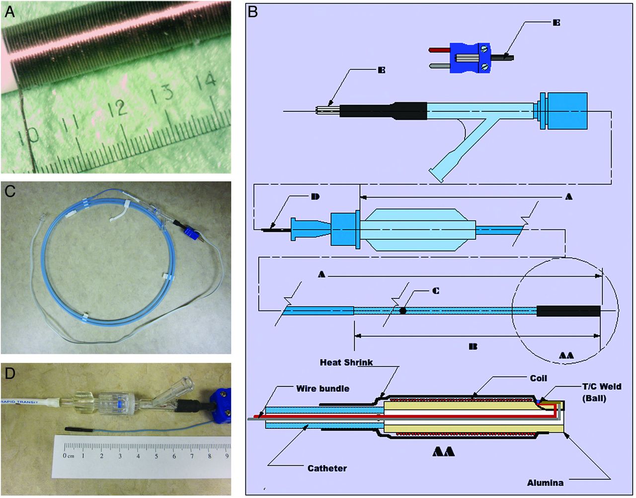
Several 2.3F RapidTransit (Codman Neurovascular, Raynham, Massachusetts) and Tracker-18 (Boston Scientific, Natick, Massachusetts) microcatheters were used as substrates for microcoils (Table 1). Copper wire (0.0015-inch) was wrapped around the outer surface of a 99.8% pure 1.3-mm outer diameter tube (Ortech Advanced Ceramics, Sacramento, California) to create solenoid coils of 30 to 75 turns (Table 1 and Fig 1A). The copper wire was wound into thermal epoxy to ensure adherence to the tube. Additional layers of epoxy and heat shrink-wrap were placed over the solenoid, resulting in a final outer diameter of approximately 2.0 mm. The heat shrink-wrap also attached the alumina tube–copper coil assembly to the distal tip of the microcatheter (Fig 1B).
Microcatheter constructs

MARC catheter system. A, Hand-wound copper coil solenoid on an alumina substrate tube. B, Catheter diagram with thermocouple. A. Catheter length. B. Catheter tip. C. Coil feedwire. D. Power lead E. Power phone jack lead AA. Catheter tip. C, Magnetic microcatheter III with thermocouple. A light blue Rapid Transit microcatheter (Cordis, Miami Lakes, Florida) with a 2.3F distal tip has been used as a substrate. A 30-turn copper solenoid coil mounted on an alumina tube is attached to the distal tip of the microcatheter with brown shrink-wrap. A copper-constantan thermocouple terminates adjacent to the coils within the shrink-wrap. Current-carrying copper wires to the solenoid coil run down the catheter lumen and are attached to a phone jack adaptor that, itself, can be plugged into a power source for activation experiments. The dark blue thermocouple plug at the catheter hub can be attached to a data logger for temperature measurements. D, Distal tip of magnetic microcatheter III. A 30-turn copper solenoid coil mounted on an alumina tube is attached to the distal tip of the microcatheter. Brown shrink-wrap attaches the alumina tube–copper coil assembly to the distal tip of the microcatheter. The final outer diameter is approximately 2 mm.
Two 0.005-inch copper H-polyinsulated wires were run through the lumen of each microcatheter. Lead wires were attached to microcoil leads located proximal to the catheter tip. Microcoil leads were made of copper wire 0.0015 inch in diameter. Coil lead wires were 2.5 and 3.25 inches long. Coil lead wires allowed separation of the electrical connection point from the tip while maintaining a patent central catheter lumen. The leads were drawn through a modified Thuoy-Borst Y-adaptor (Abbott Vascular, Abbott Park, Illinois) at the microcatheter hub and were subsequently attached to the catheter. Power leads from the center 2 leads of a phone jack power adaptor were placed through the center bore of the Y-adaptor (Fig 1B, -C). The design enabled saline drip delivery through the Thuoy-Borst side port. The resistance of coils on alumina tubes ranged from 2.0 to 5.5 ω (Table 1), and the total resistance of the assembled catheter with coil tips was between 6.0 and 9.0 ω.
Microcatheter Thermocouple Construction
Two of the microcatheter constructs were designed with built-in Type T copper-constantan thermocouples (OMEGA Engineering, Stamford, Connecticut) to allow direct temperature measurement at the solenoid (Fig 1C, -D and Table 1). Three copper-coated 99.9% pure wires (0.004-inch diameter) and one 0.004-inch-diameter constantan wire were pulled through the microcatheter. One copper wire and the constantan wire were used to form the Type T thermocouple (welded ball, Fig 1B). The lead ends were attached to a Type T thermocouple jack. The catheter thermocouple was plugged into a copper/constantan lead of 0.025-inch wires 0.91 meter long.
In vitro heating experiments were performed with a microcatheter containing 2 thermocouples. The first thermocouple was buried into the far end of the alumina tube. A slot was machined in to the alumina, and the ball of the thermocouple was wedged into it approximately 0.025 inch from the end of the solenoid coil (Fig 1B). This allowed the temperature of the coil tip to be measured. The second thermocouple was mounted on the surface of heat shrink-wrap over the top of the coil area on the same radial axis as the first thermocouple. This external thermocouple allowed temperature measurement outside of the heat shrink-wrap of the microcatheter construct. A HH66U hand-held thermocouple thermometer (OMEGA Engineering) was used for temperature measurements.
In Vitro Heating Experiments
To examine the heating properties of copper solenoids on alumina tubes, we performed several benchtop-heating experiments. Hand-wound copper coils (30 turns of 1-mm copper wire) with a resistance of 0.25 ω were wound onto the alumina tube (1.26-mm outer diameter and wall thickness of 0.45 mm) substrates. Black heat shrink-wrap was placed over the solenoid tip, resulting in approximately 0.31 mm of insulation after shrinking. The 2 thermocouples were then assembled as discussed above.
Three sets of experiments were conducted, each involving temperature measurements at the coil and outside the heat shrink-wrap at current levels ranging from 10 mA to 700 mA. In a single set of experiments, water (2 mL/minute) flowed through the catheter lumen and through the alumina tube. Two other sets of experiments were performed with no flow, but the coil was immersed in water at 25°C and 37°C.
In Vivo Testing at 1.5T
Eight 30-kg farm pigs were used to investigate potential thermal damage from resistive or RF heating related to use of the microcoil-tipped catheter, under a protocol approved by the University of California, San Francisco Institutional Committee on Animal Care and Research. Each pig fasted for 12 hours before the experiment and before being premedicated with acepromazine (1.1 mg/kg IV) and ketamine (20–30 mg/kg); intubated; and anesthetized with 1.5%–2.5% isoflurane, 2%–3% nitrous oxide, and 100% oxygen throughout the study.
A 9F vascular sheath was inserted into the femoral artery percutaneously under aseptic conditions. Immediately afterward, heparin (50 IU/kg IV) was administered. Under x-ray guidance (Philips V5000; Best, the Netherlands, or OEC Medical Systems 9600; GE Healthcare, Milwaukee, Wisconsin), either a 9F balloon guide catheter (Concentric Medical, Mountain View, California) or an 8F MPC Envoy guide catheter (Codman) was navigated coaxially over a 5F vertebral artery catheter (Cook Medical, Bloomington, Indiana) and a 0.035-inch Bentson guidewire (Boston Scientific) to the proximal left or right CCA. The inner catheter and guidewire were removed, and the guide catheter was double-flushed and perfused with room-temperature normal saline solution at a variable drip rate depending on the desired experimental conditions (On-line Tables). Next, the coil-tipped microcatheter construct was inserted through the guide catheter and was advanced to the proximal ECA under x-ray fluoroscopic road-mapping by use of iohexol contrast (Omnipaque 300; GE Healthcare), diluted 1:1 with normal saline. The animal was moved to the 1.5T MR imaging scanner (Achieva; Philips) along a single sliding table in the University of California, San Francisco's combined x-ray/MR imaging suite. Imaging and catheter-heating experiments were then performed under MR imaging guidance in the ECA and CCA as outlined below.
After the procedures were performed in 1 carotid artery, the pig was moved to the x-ray angiography suite for catheterization of the contralateral proximal CCA with the guide catheter as above. The coil-tipped microcatheter was reinserted through the guide catheter and was advanced to the proximal ECA. In 4 animals, the CCA was then occluded at the tip of the guide catheter (several centimeters proximal to the microcoil-tipped catheter) either via guide catheter balloon inflation or surgical silk suture ligature. The animal was then transported to the MR imaging scanner in preparation for repeated imaging and heating experiments as outlined below.
In Vivo Imaging and Heating Experiments
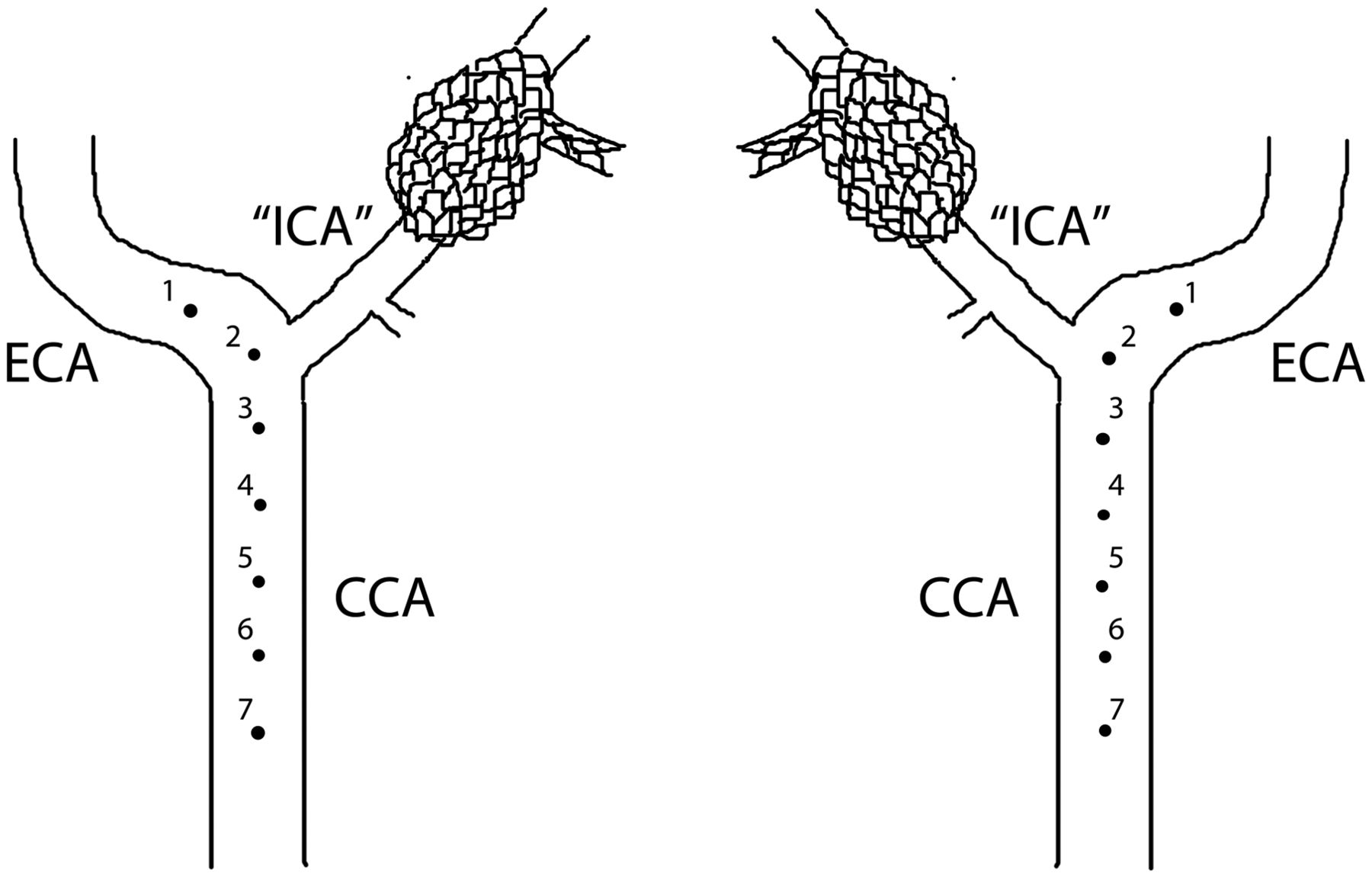
Microcatheters were activated at 6–7 positions in each carotid artery, with the most distal test-point in the proximal ECA (1 cm distal to the origin of the ascending pharyngeal artery, which is the equivalent of the internal carotid artery in pigs) and subsequent test-points more proximal in the CCA (Fig 2). Microcatheters were manually pulled back 1 cm (confirmed by imaging) between each successive activation point in the carotid artery. This was performed to ensure adequate spacing between points if thermal or mechanical damage occurred at any given point. Activations with up to 700 mA of catheter-tip current for various durations of time were directed at testing resistive heating caused by running current through the catheter coils during imaging. In contrast, sham activation points that were performed with no current (0 mA for 0.5, 1, or 5 minutes) were directed at investigating potential radio frequency heating from imaging alone, as well as assessing potential mechanical damage to the vessel walls from catheterization. Imaging was performed with an SSFP sequence (TR, 5.5 ms; TE, 1.6 ms; flip angle, 30°; matrix, 128 × 128; section thickness, 5–6 mm; specific absorption rate, 3.7 W/kg), with real-time imaging at 3–5 frames per second.

Schematic diagram depicting coil-tipped microcatheter heating activation points in vivo (swine right and left common carotid arteries, respectively). The first activation point is 1 cm distal to the origin of the internal carotid artery (ascending pharyngeal artery). Each subsequent activation point is separated by a 1-cm manual pull-back of the catheter, confirmed by imaging. This ensures adequate spacing between points in case of potential thermal damage to the arterial wall at any given point.
Euthanasia and Postmortem Gross and Histologic Analyses
On completion of imaging, both the guide and the microcoil-tipped catheters were carefully withdrawn from the femoral access site and were examined for blood clots. Animals were permitted to remain under anesthesia for 4 to 5 additional hours to provide sufficient time for evolution of vascular changes related to thermal or mechanical damage. Euthanasia was performed by injection of saturated potassium chloride (1 mL/kg IV), and bilateral thoracotomy. The carotid arteries were isolated, excised en bloc, and opened longitudinally for gross examination. They were then fixed in 10% buffered formalin and embedded in paraffin in preparation for histologic staining. Arteries were sectioned into 5-μm-thick cross-sections and were subsequently stained with hematoxylin-eosin, Masson trichrome, and cleaved caspase 3 stain. Microscopic analyses were performed on all sections to evaluate any thermal or mechanical damage to the arterial walls. Composite gross and histologic damage scoring of samples was separated into 3 levels: 0 = normal arterial wall and lumen, 1 = questionable damage (endothelial denudation, subtle changes to vessel wall, small amount of luminal thrombus adherent to endothelial surface), and 2 = definite thermal damage (infiltration of inflammatory cells into vessel wall, mural hemorrhage, endothelial disruption). Histologic damage data were analyzed with STATA SE version 10 (StataCorp, College Station, Texas), by use of a case-control odds ratio calculator, 2-sided Fisher exact tests, and Wilcoxon log-rank sum tests.
Results
In Vitro Testing
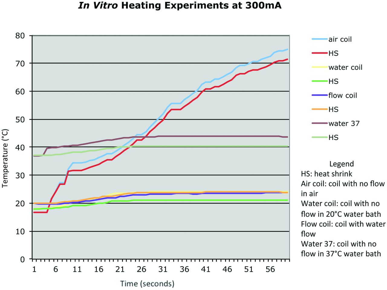
Benchtop heating experiments demonstrated temperatures at thermocouple 2 outside of the heat shrink-wrap were significantly lower than temperatures at thermocouple 1 at the coil because of the insulating effect of the heat shrink-wrap (Fig 3). For example, in experiments at 500 mA without luminal flow, the increase in temperature at the outer surface of the catheter tip was roughly 10°C less than it would be in the absence of shrink-wrap. Higher currents correlated with higher temperatures at both thermocouples but also a larger temperature difference between thermocouple 1 and thermocouple 2.

In vitro heating data for alumina tube construct tested at 300 mA in air, in a 25°C water bath, and in a 37°C water bath.
With the addition of 2-mL/minute water flow through the catheter lumen, temperature rise at both thermocouples was significantly decreased. At 500 mA of current, the coil was 18°C without flow and 11°C with flow. There was also a much smaller temperature decrease across the heat shrink-wrap with flow than without, indicating that most of the heat from the coils flows inward rather than outward.
Coils made of insulated copper wire result in large increases in temperature at high currents. Thermal resistance between the coil and alumina substrate accounted for a temperature increase of the coil of > 10°C with luminal saline flow at 2 mL/minute. For coils fabricated directly on the alumina, the thermal barrier of the wire insulation is absent and much lower temperature increases are observed.7
In Vivo Catheter Visualization
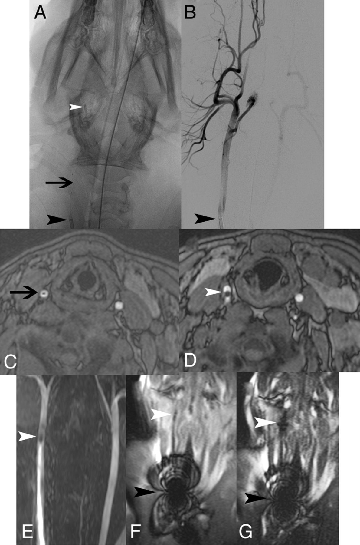
It was possible to visualize the MARC in vivo in porcine carotid arteries under x-ray fluoroscopic, time-of-flight MRA, and SSFP MR imaging (Fig 4). The MARC tip was visible on unsubtracted x-ray fluoroscopy (Fig 4A) but was difficult to see on x-ray angiography (Fig 4B). The MARC shaft (Fig 4C) and tip (Fig 4D) were clearly evident on axial MRA, and the MARC tip was easily visible on coronally reformatted MRA MIP (Fig 4E). Whereas the guiding catheter used to reach the proximal CCA demonstrated extensive MR imaging artifacts because of a metallic marker band at the catheter tip (Fig 4F, -G), the MARC tip was barely visible without current activation on SSFP (Fig 4F) and was easily visible when current was running through the catheter tip coils (Fig 4G). MR imaging, MRA, and x-ray were used to confirm MARC positioning before each tip coil current activation experiment. MR imaging, MRA, and x-ray angiography did not demonstrate changes in vessel caliber or macroscopic luminal thrombus after the activation experiments.

In vivo x-ray, DSA, axial MRA, coronal MRA MIP, and coronal SSFP. Unsubtracted x-ray image (A) demonstrates MARC catheter tip coils (white arrowhead), microcatheter shaft with lead wires (black arrow), and guiding catheter (black arrowhead) in the right CCA. Only the guiding catheter tip marker is readily evident on the equivalent DSA image (B). Susceptibility from the catheter shaft lead wires (black arrow) and catheter tip (white arrowhead) is seen on axial MRA (C and D), coronal MRA MIP (E), and coronal SSFP (F). With a 300-mA current applied (G), the catheter tip coils are more apparent (white arrowhead). Guide catheter tip artifacts resulting from a metallic marker band are very prominent on the SSFP sequence (F and G).
In Vivo Catheter Activation–Related Heating
A total of 94 current activation experiments were performed in 8 pigs (16 carotid arteries). The principal variables examined for pair-wise comparisons on the likelihood of vessel wall damage include normal carotid arterial flow vs arterial stasis, amount of current applied to the MARC tip (≤300 mA vs > 300 mA), duration of MARC tip current activation (≤1 minute vs > 1 minute), estimated energy dissipation, rate of guide catheter saline drip, catheter tip coil temperature measured within the MARC tip shrink-wrap, and guidance under MR imaging and x-ray vs x-ray alone (Tables 2 and 3).
Definite vs no or questionable histologic damage to carotid arteries under various conditions of catheter testing in vivo
Definite or questionable vs no histologic damage to carotid arteries under various conditions of catheter testing in vivo
Three sets of conditions demonstrated significant differences in the likelihood of vascular damage both by use of the criterion of definite histologic damage or the more conservative criterion of definite or questionable histologic damage: ≤300-mA catheter tip current activations vs > 300mA (less damage with less current), ≤100 J of energy delivered vs > 100 J (less damage with less energy), and ≤5°C MARC catheter tip coil temperature increase (measured at the thermocouple immediately adjacent to the coil within the shrink-wrap at the tip of the catheter) vs > 5°C (less damage with less temperature increase). As energy (work) equals the square of current × resistance × duration of activation, the relevant parameters were multiplied for each catheter system activation by use of the resistances measured in Table 1. This calculation assumes that the resistance of the catheter system does not change with temperature. Temperature increases measured at the MARC coils ranged from 0°C for zero current to 16°C for 600-mA current (On-line Tables). MARC coil activations of ≤1 minute vs > 1 minute did not differ in the likelihood of definite histologic damage (OR, 0.37; 95% CI, 0.056–1.9; P = .29), but by use of the more conservative criterion of definite or questionable histologic damage, shorter activations were less likely to be associated with histologic changes (OR, 0.17; 95% CI, 0.037–0.61; P = .003).
Of 70 activations performed under normal arterial flow conditions, more samples had histologic changes than those under carotid artery stasis by use of both the definite damage criterion (Table 2) and the more conservative definite or questionable histologic changes criterion (Table 3). This is counterintuitive but may relate to the ability of inflammatory cells to access the vascular wall after arterial stasis, though carotid arteries were reperfused after catheter tip activations.
In vivo vascular heating experiments were performed both in the MR imaging scanner and under x-ray guidance alone, to assess potential effect of the MR environment (strong magnetic field and SSFP imaging sequence with concomitant RF energy deposition) on tissue heating. No significant differences in the odds of histologic changes or definite damage were evident between the group receiving x-ray only and the group receiving x-ray plus MR imaging (Tables 2 and 3).
Subset Analysis
The degree of histologic damage identified at various current levels under normal carotid flow vs carotid stasis is displayed in Fig 5 and categorized in Fig 6. Under normal carotid arterial flow, with 0 (0%) of 43 activations with ≤300-mA MARC tip current resulted in definite histologic damage, whereas 8 (30%) of 27 activations with > 300 mA resulted in definite histologic damage (OR, 0; 95% CI, 0–0.23; P = .0002). With use of the more conservative criterion of definite or questionable histologic damage, under normal carotid arterial flow, with ≤300-mA tip current 5 (12%) of 43 had definite or questionable damage vs 8 (30%) of 27 with > 300 mA (OR, 0.31; 95% CI, 0.71–1.3; P = .11).

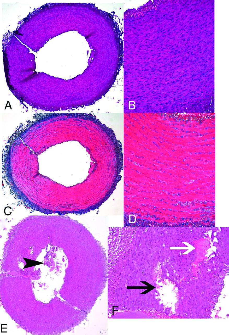
Porcine carotid artery wall histologic appearance after use of endovascular catheter tip coils at a 300-mA tip current for 1 minute at normal flow (A-D) or a 600-mA tip current for 2 minutes at zero flow (E and F). There is no evidence of vessel wall damage on hematoxylin-eosin (A and B) or Masson trichrome (C and D) at 300 mA. At 600 mA, however, luminal thrombus (E, black arrowhead), extensive medial vacuolization (F, black arrow), and medial hemorrhage (G, white arrow) all indicate thermal damage to the arterial wall.

Plot of applied current vs degree of histologic damage for catheter activation experiments in vivo (n=94) in porcine carotid arteries. A, Normal arterial flow. B, Arterial stasis.
Discussion
Preliminary in vivo testing of coil-tipped magnetically remote-controlled catheters at a microcatheter tip current of 0 to 700 mA demonstrated damage to carotid artery walls under several conditions when more than 300 mA of current was applied to the catheter tip. Lesser amounts of current did not result in infiltration of inflammatory cells into the carotid artery wall, but a few samples, even at 0 mA of tip current, did show evidence of endothelial denudation. This was likely the result of the mechanical force of the catheter tip against the blood vessel wall, as can happen with any endovascular device.11,12
One of the limitations of our study was its inability to discriminate between endothelial damage caused by heating compared with mechanical forces. Our MARC catheter has various mechanical features that differ from conventional catheters. Conventional neurovascular microcatheters usually contain radiopaque metallic bands (approximately 1 mm long) at the tip (and often 3 cm proximal to the tip) that are used as markers during procedures performed under x-ray. The MARC catheter contains copper microcoils at the tip that produce distinct artifacts during MR imaging that serve as an indicator of catheter tip position. In addition, the MARC catheter tip (approximately 1 cm) is stiffer and of slightly greater diameter than conventional neurovascular microcatheter tips. The present length of the stiff alumina tube at the MARC tip may ultimately impair its ability to have the desirable tight turning radius for navigating small vessels. Rigid devices are also more likely than soft devices to put greater forces on vascular walls, potentially leading to endothelial denudation or mural dissection. These differences warrant consideration of mechanical as well as thermal damage caused by the MARC to evaluate overall safety in vivo.
The potential for mechanical damage to vessel walls was mitigated throughout our experiments by use of a solenoid coil whose generated magnetic moment aligns with the bore of the MR imaging scanner (and thus aligns with B0) when the MARC is placed in the carotid artery (which also aligns with the bore of the MR imaging scanner). Thus, current activations, to a first approximation, should not force the catheter into the wall of the carotid artery. Initial placement of the relatively stiff-tipped catheter into the distal carotid artery may scrape the walls of the vessel and cause damage.
As the degree of vascular damage did not differ between tests performed in the MR imaging scanner (in which RF heating during imaging is a potential concern)8 and those performed solely under x-ray guidance, there is likely a negligible contribution of RF energy absorption to catheter heating under the conditions tested. Instead, reducing resistive heating of the catheter tip coils during navigation current activation remains the primary challenge for developing a functional MARC system for remote-control catheter steering under MR imaging guidance.
Reductions in heat deposited by the MARC tip coils at the brief (< 30-second), low currents (< 300 mA) required for useful tip deflection at 1.5T can be addressed in several ways. First, room temperature or cooled saline irrigation to guide catheters and MARC catheters can reduce heating. This approach is similar to that used in the cooling of electrophysiology catheters used in MR imaging: mitigation of temperature increase (from > 22°C to <2°C) with electrophysiology catheters has been achieved with irrigation rates of 2 mL/min at 1W and 10–14 mL/min at 5W.13 As the MARC catheter has a power output of approximately 1.2W at 300 mA currents, irrigation at rates we have achieved experimentally would be expected to increase the safety of our device. Second, the manufacture of MARC tip coils directly on substrate alumina tubes with laser lithography versus the present use of hand-wound insulated copper wires would be expected to reduce heating, because lithographed coils would have a larger contact surface area with the highly thermally conductive alumina than round insulated wires, which only contact the alumina over a small percentage of their surface. Third, optimizing the catheter design (eg, with coaxial chokes on the catheter shaft current-carrying wires to mitigate potential RF-induced heating during MR imaging) would also contribute to device safety.14
Direct intravascular temperature measurements are challenging in MR imaging, thus explaining our choice of histologic features as the endpoint for analysis of potential thermal damage in the experiments presented. MR imaging thermometry typically involves measurements of proton resonance frequency or molecular motion, which are overwhelmed by the flow of blood and the artifacts generated by microcoil activation. Fiberoptic temperature sensors are presently not small enough in caliber to be included as part of a microcatheter system. Thermocouples on our endovascular catheters were able to measure temperatures adjacent to the MARC coils immediately before and after SSFP imaging, but not during imaging, probably because of RF interference. It may be possible to develop an interleaved imaging, navigation, and temperature-sensing strategy in which temperature measurements are taken from a catheter tip thermocouple during short pauses in imaging.
Our experimental design addressed only the simplest MARC tip coil geometry and device and vascular alignment in the MR imaging scanner bore. As the MARC system is developed further, non-solenoid steering coils (such as Helmholz saddle-shaped coils) will be required for navigating in different planes. These different coil geometries—and particularly multilevel designs with solenoids on an outer layer and saddle coils on an inner layer—may have different heating properties and will certainly have different mechanical properties than the conditions tested herein. Blood vessel branches can arise in many orientations relative to parent vessels. Remote-controlled navigation into various vascular branches will require different amounts of electrical current delivered to the MARC catheter depending not only on the angle at which the target vessel arises, but also depending on the orientation of the catheter tip relative to the bore of the MR imaging scanner. Determining in real-time the amount of current that needs to be delivered to the MARC coils for the spectrum of possible vascular configurations is an ongoing challenge that will have to be developed in parallel with new steering coil designs.
Conclusions
Preliminary in vivo testing of coil-tipped magnetically remote-controlled catheters demonstrated minimal injury to vessel walls when currents of ≤300 mA were applied. As prior experiments have suggested useful catheter tip deflection at similarly low currents, future experiments will evaluate navigation at currents < 300 mA to maximize potential safety.
Acknowledgments
The authors would like to thank Carol Stillson, Timothy Roberts, Pallav Kolli, Daniel Cooke, Matthew Amans, and Robert Taylor.
Footnotes
Disclosures: Steven Hetts—RELATED: Grant: ASNR,* NIH,* Comments: ASNR Foundation Scholar Award; NIH-NIBIB R01 Research Grant; UNRELATED: Consultancy: Silk Road Medical, Comments: Consultation on a medical device startup company; not related to the work presented. Alastair Martin—RELATED: Grant: NIH.* Anthony Bernhardt—RELATED: Grant: NIH.* Fabio Settecase—RELATED: Grant: NIH grant R01EB012031–02,* Comments: “Endovascular Magnetic Catheter for Interventional MRI,” Principal Investigator: Steven W. Hetts; UNRELATED: Grants/Grants Pending: NIH grant R01EB012031–02.* Shuvo Roy—RELATED: Grant: NIH,* Comments: Grant to Steven Hetts (PI). Ronald Arenson—RELATED: Grant: NIH R01 1R01EB012031–01,* Comments: I am listed as consultant but have not received any payments; UNRELATED: Board Membership: Radiological Society of North America (RSNA), Comments: Board of Directors—paid for travel including for spouse and upgrades to business class; Grants/Grants Pending: NIH via RSNA;* Payment for Lectures (including service on speaker bureaus): Stanford University, Ochsner Clinic, Comments: Honorarium for speaking; Patents (planned, pending or issued): Patent for catheter design, Comments: I hold the patent, which is the subject of this manuscript, but I have not received any royalties because it has not been licensed yet; Stock/Stock Options: Retirement funds, Comments: All managed by third parties; Travel/Accommodations/Meeting Expenses Unrelated to Activities Listed: University of California, San Francisco, Comments: Reimbursement from UCSF for professional travel; OTHER RELATIONSHIPS: Some readers could conceivably believe the fact that I hold the patent influenced the work. Mark Wilson—RELATED: Grant: NIH.* *Money paid to institution.
This study was supported by American Society of Neuroradiology Research and Education Foundation Scholar Award 2010 and 2011 (S.W.H.), National Heart Lung Blood Institute, National Institutes of Health (NIH), through M. Wilson Grant Number 1R01HL076486, National Institute of Biomedical Imaging and Bioengineering, NIH, through Grant Number 1R01EB012031-01A1 (S.W.H.), and National Center for Research Resources and the National Center for Advancing Translational Sciences, NIH, through UCSF-CTSI Grant Number UL1 RR024131, National Institute of on Minority Health and Health Disparities, NIH, through Grant Number R25MD006832. Its contents are solely the responsibility of the authors and do not necessarily represent the official views of the American Society of Neuroradiology or the NIH.
Paper previously presented in part at: Annual Meeting of the American Society of Neuroradiology, April 23, 2012; New York, New York.
Indicates open access to non-subscribers at www.ajnr.org
REFERENCES
- Received September 5, 2012.
- Accepted after revision December 27, 2012.
- © 2013 by American Journal of Neuroradiology


Jump to section
Related Articles
Cited By...
- No citing articles found.